ASSEMBLy
10
NOTE: When using string trimmer head, use only .080
Inch (2mm) diameter line.
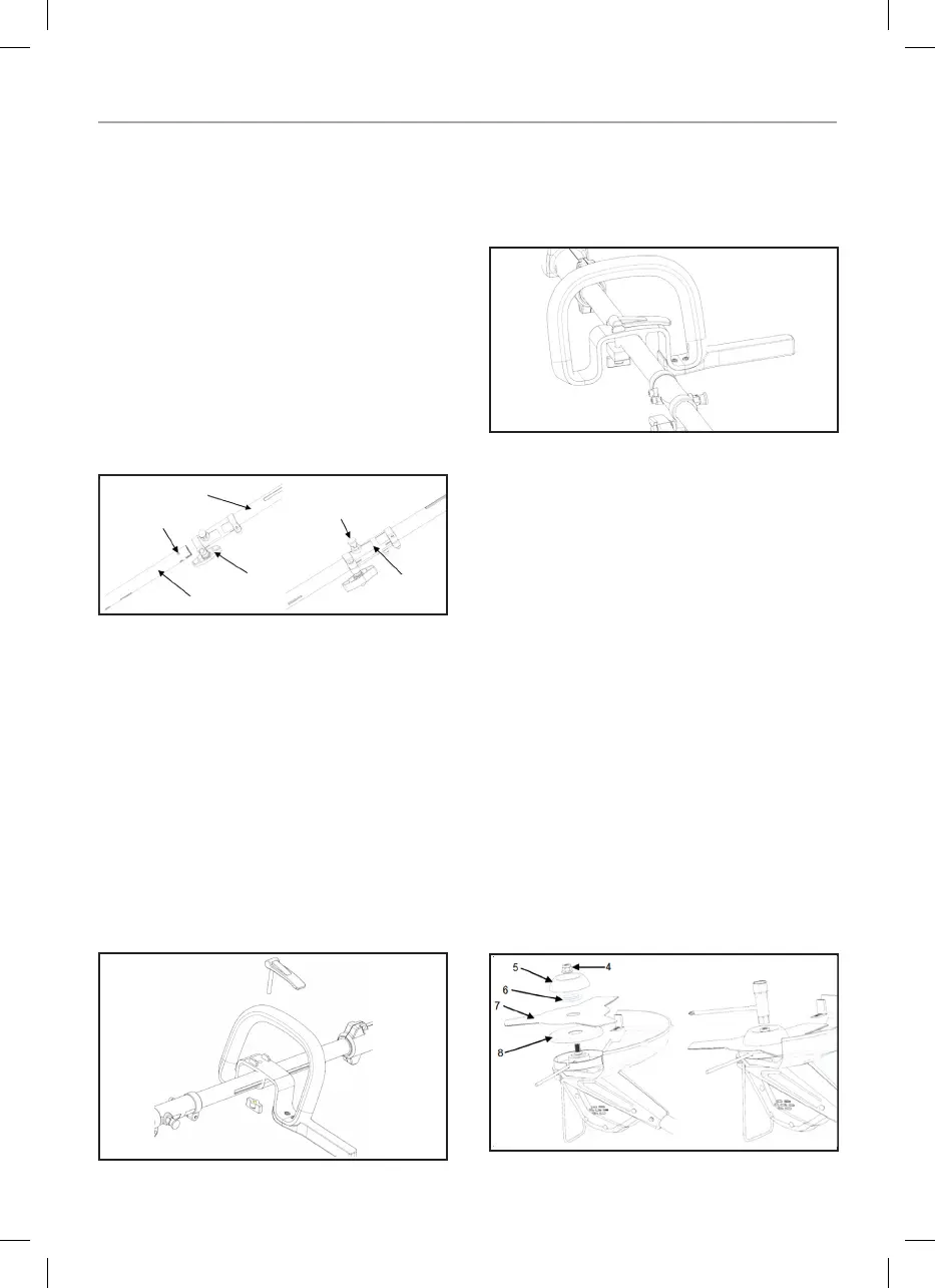
– Loosen the lock knob on the coupler.
– Pull up the positioning column (it can be fixed by
rotating at a certain Angle), align the front-end tube
with the back-end tube and insert it, rotate the front
end tube in a small range to clamp the positioning
column into the positioning hole, positioning column
should go down on it own when located correctly.
– Turn the locking knob to tighten back up.
NOTE: If the positioning column does not release
completely in the positioning hole, the tubes are not
locked into place. Slightly rotate from side to side until
the positioning column is locked into place.
When required to separate the front-end tube from the
back-end tube.
– Stop the tool.
– Remove the battery from the rear handle.
– Loosen the lock knob on the coupler.
– Pull up the positioning column and rotate the front-
end tube to separate the two ends of the machine.
(4) ASSEMBLING AUXILIARY HANDLE
– Take out the auxiliary handle, unscrew the knob,
remove the bolt, and align the auxiliary handle
with the slot in the tube and snap it in through the
opening.
– Move the assist handle back and forth to find a
comfortable position.
– Thread the bolt through the hole in the auxiliary
handle and lock the knob.
(5) INSTALLATION OF SHOULDER HARNESS AND
WIRE RACK
– Hook a shoulder harness to the Rear handle.
– Clamp the wire rack into the appropriate clamping
position of the machine head.
CUTTING SHRUBS FUNCTION
ASSEMBLY
– Stop the tool.
– Remove the battery from the rear handle.
– Remove the trimmer head.
– Take out nut (4), protection cover (5), pressure plate
(6), 10’’knife plate (7) and protection cover prevent
tangling (8).
– Install the five parts on the machine head in
sequence as shown in the picture, insert the
round rod to fix the shaft and tighten the nut
counterclockwise with a cross slot spanner.
– Remove the round rod after installation.
Back-end Tube
Position Hole
Front End Tube
Lock Knob
Positioning Column
Coupler