Do you have a question about the Watlow EZ-ZONE PM Series and is the answer not in the manual?
Outlines the product warranty terms and conditions.
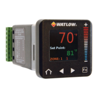
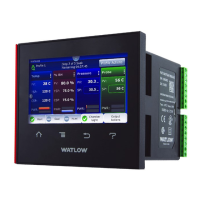
Describes the EZ-ZONE PM Express controller and its package options.
Provides physical dimensions for the 1/32 DIN controller.
Details recommended panel cutout and spacing for the 1/32 DIN model.
Provides physical dimensions for the 1/16 DIN controller.
Details recommended panel cutout and spacing for the 1/16 DIN model.
Provides physical dimensions for the 1/8 DIN vertical controller.
Details recommended panel cutout and spacing for the 1/8 DIN vertical model.
Provides physical dimensions for the 1/8 DIN horizontal controller.
Details recommended panel cutout and spacing for the 1/8 DIN horizontal model.
Provides physical dimensions for the 1/4 DIN controller.
Details recommended panel cutout and spacing for the 1/4 DIN model.
Instructions on how to detach the controller from its case.
Steps for re-inserting the controller into its mounting case.
Lists materials compatible and incompatible with the product.
Defines terminals for Slot C, including power input and bus communication.
Defines terminals for Slot A, supporting universal sensor inputs.
Defines terminals for controller outputs, including relay and open collector types.
Illustrates terminal configurations for PM3 and PM6 models.
Illustrates terminal configurations for PM8, PM4, and PM9 models.
Specifies maximum wire size, termination, and torque requirements.
Details AC/DC voltage ranges and power consumption for various models.
Describes connection and specifications for voltage and current inputs.
Details RTD input types, calibration, and lead resistance considerations.
Covers thermocouple and thermistor input specifications and wiring.
Explains setup and specifications for Form C and Form A mechanical relay outputs.
Details configuration and use of open collector and switched DC outputs.
Specifies resistive load, pilot duty, and lifespan for Form C and Form A relays.
Provides current, voltage, and load control details for Switched DC and Open Collector.
Explains buttons, displays, and indicators for the 16th DIN model.
Describes buttons and displays for the 32nd DIN controller.
Shows keypad and display elements for 1/8 DIN PM8 and PM9 controllers.
Illustrates the keypad and display elements for the 1/4 DIN PM4 controller.
Explains how to interpret and respond to error and alarm messages.
Details parameters for setting low and high process limits.
Explains parameters for configuring low and high alarm set points.
Describes how to set an offset value for process output calibration.
Shows the valid range of values for limit set points.
Displays the valid range of values for alarm set points.
Indicates the valid range for the calibration offset parameter.
Configures security, sensor type, and thermocouple linearization.
Selects thermistor curves, resistance range, and display decimal precision.
Sets display units and the low limit for set point adjustment.
Shows valid range values for lockout, sensor type, and linearization.
Displays range values for thermistor curve, resistance, and decimal precision.
Provides range values for display units and low limit set points.
Sets high limit set point and configures output functions for Output 1 and 2.
Defines monitored sides of process value and sets limit hysteresis.
Configures alarm tracking and hysteresis for alarms.
Sets the output condition during an alarm and alarm blocking behavior.
Enables alarm silencing and controls alarm message display.
Provides options for limit state and alarm set point monitoring.
Configures alarm latching behavior and when alarms are blocked.
Manages alarm silencing and display options.
Selects display parameters and sets the zone address for communication.
Configures alarm latching behavior and when alarms are blocked.
Manages alarm silencing and display options.
Provides options for limit state and alarm set point monitoring.
Details voltage requirements and power consumption for different models.
Specifies operating temperature, storage, humidity, and accuracy metrics.
Lists certifications and compliance standards met by the product.
Details accuracy, error ranges, and units for thermistor inputs.
Lists third-party thermistor compatibility and built-in linearization curves.
Details specifications for switched DC, open collector, and relay outputs.
Explains the coding system for ordering part numbers and their options.
Lists compliance with EU Electromagnetic Compatibility and Low-Voltage Directives.
Details compliance with RoHS, WEEE, SEMI F47, and other relevant directives.
Provides contact details for Watlow offices worldwide.
| Input Voltage | 24 VAC/DC |
|---|---|
| Control Type | PID |
| Output Type | Relay, SSR, Analog |
| Communication Protocols | Modbus RTU, Ethernet/IP, Profibus |
| Input Types | Thermocouple, RTD |
| Alarms | Deviation High/Low |
| Approvals | CE, UL |
| Configuration | Front panel, PC software |
| Enclosure Rating | NEMA 4X |


 Loading...