Do you have a question about the Watlow 97 series and is the answer not in the manual?
Procedure for installing the Series 97 controller into a panel cutout, including gasket seating and mounting.
Details on wiring options, input-to-output isolation, and modular design of the Series 97.
Information on connecting the Series 97 controller to power sources, including voltage specifications.
Specific wiring diagrams and instructions for Input 1, supporting Thermocouple and RTD sensors.
Wiring instructions for Input 2, covering Digital Event inputs like voltage and contact closure.
Details on wiring Output 1 for limit control, including AC output specifications.
Wiring configurations for Output 2 as an alarm, covering AC outputs and switched DC.
Wiring instructions for Output 3 functioning as an alarm, detailing AC output configurations.
Wiring for Output 4, including AC outputs and communications/retransmit options.
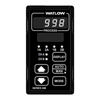
Overview of the Series 97 controller's keys, displays, and indicator lights.
Instructions on how to navigate through different pages and menus on the Series 97 controller.
Details on configuring alarms, including set points, hysteresis, latching, and silencing.
Information on programming and monitoring the Series 97 via serial communications (EIA/TIA-485/232).
Provides a recommended sequence for setting up controller parameters for optimal configuration.
Lists the 8 menus available within the Setup Page for configuring controller settings.
Procedures for calibrating thermocouple and RTD inputs.
Lists common indications, their probable causes, and corrective actions for alarms and errors.
Explains the Modbus RTU protocol for communication and controlling the Series 97 controller.
Detailed procedures for calibrating various inputs and outputs of the Series 97 controller.
| Type | Temperature Controller |
|---|---|
| Control Algorithm | PID, On/Off |
| Input Type | Thermocouple, RTD, Process |
| Output Type | Relay |
| Display | LED |
| Power Supply | 24 VAC/VDC, 100-240 VAC |
| Communication Protocol | RS-485 |
| Enclosure Rating | NEMA 4X |


 Loading...