Do you have a question about the Watlow Ez-Zone PM6 and is the answer not in the manual?
Explains safety symbols and their meanings.
Details product warranty and how to obtain technical support.
Outlines the steps for returning products for repair or evaluation.
Details the key features, advantages, and agency approvals of the EZ-ZONE PM.
Explains the controller's internal structure: inputs, functions, and outputs.
Provides physical dimensions and panel cutout specifications for various models.
Details how to install the controller into a panel and remove it.
Defines terminal connections for Slot A and Slot C, and shows back views.
Describes power supply requirements and wiring for digital inputs 5 and 6.
Details wiring for various analog input types: Thermocouple, RTD, Process, Potentiometer.
Explains wiring for digital outputs, switched DC, and mechanical relays.
Details wiring for Universal Process and Switched DC outputs.
Details wiring for NO-ARC Relay, Mechanical Relay, and Solid-state Relay outputs.
Guides for wiring EIA-485 Standard Bus and Modbus RTU networks.
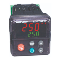
Describes the function of each key, display, and indicator on the controller.
Explains how to interpret and respond to alarm and error messages.
Details how to set up the Home Page, change parameters, and navigate between pages.
Explains the meaning of terms and symbols used in the manual's menu descriptions.
Outlines the main menus within the Operations Page: Analog Input, Loop, Alarm, etc.
Details parameters for Process Value, Error Status, and Calibration Offset.
Describes parameters for Source Value, Offset, Output Value, and error reporting.
Covers parameters for digital I/O states, set points, and control mode.
Details parameters for Cool Power, Set Point, Remote Enable, Control Mode, and Autotune.
Covers parameters for Idle Set Point, PID tuning constants, and Alarm Low/High Set Points.
Details parameters for Alarm State, Clearable, Request, Silence, and Profile Start.
Describes parameters for Action Request, Active Step, Step Type, Target Set Point, and Produced Set Point.
Covers parameters for Step Time Remaining, Event Outputs, Jump Count, and Profile State.
Details the parameter for indicating the currently executing profile file.
Explains how to navigate the Setup Page and configure Analog Input parameters.
Details parameters for Analog Input Scale High, Range, Error settings, and Linearization/Process Value setup.
Covers remaining Linearization points and Process Value setup parameters.
Details parameters for Digital Input/Output direction, function, and Control Loop settings.
Covers Control Loop parameters like PID tuning and Output settings.
Details setup for Digital Outputs (Time Base, Scales) and Digital Input Level.
Covers Function Key assignment, Global settings, and Communications protocols.
Details Profile settings, remaining Communications parameters, and Real Time Clock setup.
Covers remaining RTC settings and Alarm Type and Source parameters.
Details Alarm Hysteresis, Logic, Sides, Latching, Blocking, Silencing, Display, and Delay parameters.
Explains how to access the Profiling Page and configure Step, Step Type, and Set Point.
Covers parameters for Seconds, Wait For Process, Wait Event, Day of Week, and Jump Step.
Details parameters for Jump Count, End Type, and Profile Event Outputs.
Explains how to access the Factory Page and configure Custom Setup parameters.
Details Security settings for pages and passwords, and diagnostic information.
Covers remaining Diagnostics parameters and Calibration menu settings.
Describes saving/restoring settings, PID tuning methods, and input configuration.
Details output options like Duplex, NO-ARC Relay, Retransmit, Cool Output Curve, and Control Methods.
Explains alarm types, set points, hysteresis, and how to program EZ Keys.
Covers Password Security, enabling it, and acquiring access to the control.
Provides solutions for common alarm, error, and control problems.
Addresses issues like process control failure, temperature runaway, device errors, and communication problems.
Lists voltage, power, environmental operating conditions, and accuracy ratings.
Details specifications for digital I/O, output hardware, operator interface, dimensions, and weight.
Provides a guide to configuring model numbers by package size, function, I/O, and communications.
| Model | Ez-Zone PM6 |
|---|---|
| Controller Type | PID Controller |
| Output Options | Relay, SSR, Analog |
| Display | LCD |
| Number of Zones | 6 |
| Input Types | Thermocouple, RTD |
| Control Modes | ON/OFF, PID |
| Power Supply | 100-240 VAC |
| Communication | Ethernet |
| Agency Approvals | CE, UL |
| Operating Temperature | 0 to 50 °C |
| Enclosure Rating | IP65 |


 Loading...