Users Manual
MC100
MC100 DeviceNet OM 1.01 EN.doc Version: 1.01 Page 14 of 36
6 Configuring the fieldbus network to the MC100
6.1 Connecting the MC100 and the pumps for the first time
Make sure all pumps have been giving a unique address and all the pumps have been powered up.
The Flexnet is connected with MC100 and to the pumps in a multidrop network.
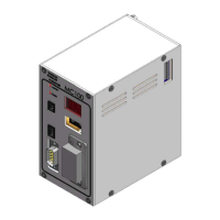
Connect SubD connector X3 to a PC using a NULL-modem cable.
Start a terminal program on the PC for example HyperTerminal.
Set the communication-parameters to: 9600 baud, 8 bits, even parity and 1 stop-bit.
When applying power to the MC100, it will identify itself by printing the line:
“ MC100 MFSC Ver. x.yy.” (x.yy will be the current version)
The MC100 will then try to identify all connected pumps on the Flexnet; the LED indicator X1 will
flicker and finally be steady green.
If for example 4 pumps are detected, the following line will be:
“Pumps: 1 2 3 4 1 4 4”
Stating that pumps numbered 1-4 are detected, lowest number is 1 and highest number is 4 totalling 4
pumps.
If the 2
nd
line is not printed and the MC12 has an Alarm indication: AL01 or AL02 flashing, it must be
investigated if the Flexnet is correct wired.
If all is OK, then continue to configure the DeviceNet scanner with RSNetWorx (see below).
 Loading...