Step 1: MODBUS HEADER TEMP SENSOR WIRING – ANY BOILER
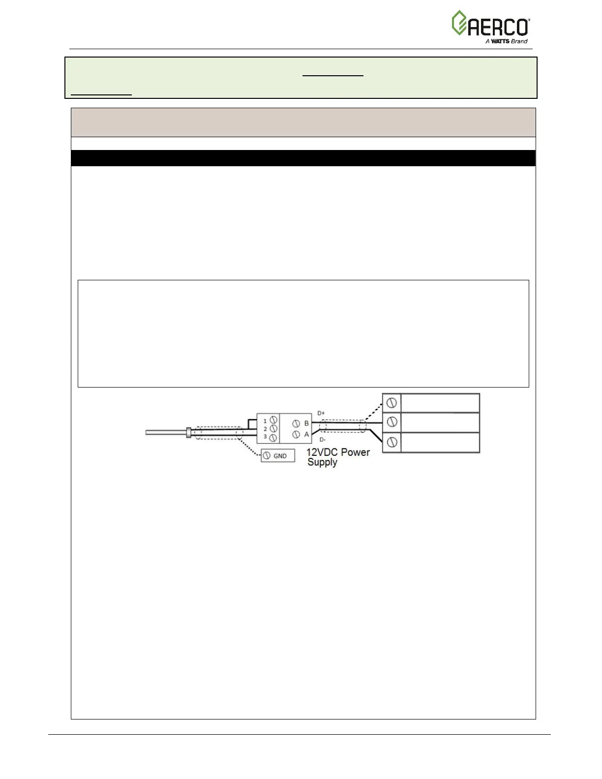
1. Connect the Modbus Transmitter terminal Pin B to the I/O board strip J3, terminal 13
(BST RS485+) and Pin A to terminal 15 (BST RS485–) on any of the Boiler units using
shielded pair 18 - 22 AWG cable.
2. Connect the shield to any Shield terminal, such as terminal 3 or 8 on strip J3.
2. Connect the Header Temp Sensor to pins 2 and 3 of the Modbus Transmitter using
shielded pair 18 - 22 AWG cable.
3. Install a jumper wire between pins 1 and 2 of the Modbus Transmitter.
NOTES:
• Polarity must be observed for the RS485 connections.
• Ground the shield to any Shield terminal on the I/O board, such as terminal 3.
• The Header Temp Sensor must be installed between 2 and 10 feet (0.61 and 3.1m)
downstream of the LAST boiler in the plant’s supply water header.
• There is no polarity to be observed. The ground for the shield is at the power supply
ground. The sensor end of the shield must be left free and ungrounded.
Continued on next page

 Loading...


