Modulex EXT Commercial Series Boilers User Manual
CHAPTER 4: Installation Instructions
Page 74 of 144 AERCO International, Inc. • 100 Oritani Dr. • Blauvelt, NY 10913 OMM-0095_0H
09/15/2017 Phone: 800-526-0288 GF-139
4.38 CONTROLS AND EMERGENCY FUNCTIONS
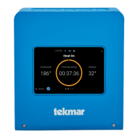
Figure 4-34: MODULEX EXT Panel Controls and Indicators
TABLE 4-8: Panel Controls and Indicators
ITEM COMPONANT/FUNCTION
A
GLT (General Limit Thermostat): when enabled, it cuts the power supply to the
boiler and lights the warning lamp (Item D). To reset, remove the cap and push
the reset button.
Main Power Switch
Fuses: 1 = 6.3 A 2 = 10 A
Warning lamp of the Thermostatic Lockout from GTL (General Limit Thermostat).
Main Switch
F*
Change-over Series/Parallel:
0 = Emergency is active or the control is managed by PLC or BMS.
I = Series connection (the cascade is managed by the BCM)
II = Parallel connection (condition of supply).
G*
In position “I” the plant will operate when requested at “CONSTANT SETPOINT”:
70°C –
Max heat output 50%.
Enables burner reset in case of lock-out.
I*
YELLOW LED = Blinking = Communication between BMM and BCM is OK.
GREEN LED = ON = Active Pump
RED LED = ON = Failure Code Detected
*See Chapter 5, section 5.2 for more information regarding the BCM (Boiler Communication
Module).
NOTE:
The emergency function enables the boiler’s burners to fire only at 50% and at 50°C in system
return. All the system’s heating loads, including the header pump, must be controlled manually.
 Loading...