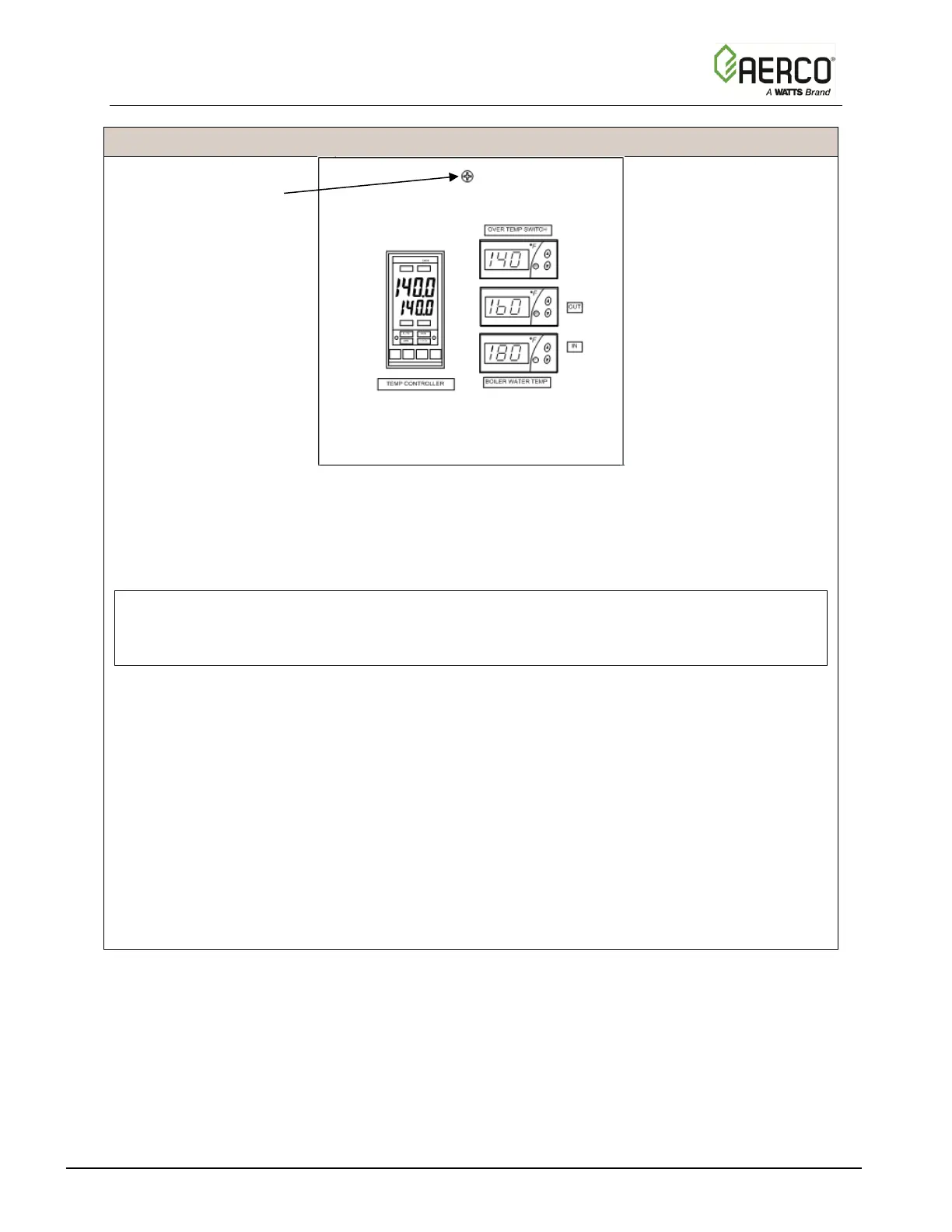
Figure 2-5. Recessed Panel Behind ECS/SP Control Box Door
3. Swing down the recessed panel to access Terminal Block TB-2 on the bottom interior
surface of the Control Box, shown in Figure 2-6.
NOTE:
Use 14 to 18 AWG wire for AC power wiring connections to the SmartPlate ECS/SP Control
Box.
4. Feed the external 120/220 VAC power leads through the cutout labeled “POWER IN” on
the bottom of the Control Box.
5. Connect the LINE, NEUTRAL and GROUND leads to the TB-2 terminals shown in Figure
2-6.
6. Check the connection of wire #100 on the right side of TB-2 to ensure the power is routed
to the proper connection for the 24 VAC transformer. If the incoming power is 120 VAC,
wire #100 should be connected to the terminal with a black wire and the orange wire
should have nothing connected to its terminal. Conversely, if the incoming power is 220
VAC, wire #100 should be connected to the terminal with the orange wire and the black
wire left unconnected.

 Loading...

