SmartPlate Installation, Operation & Maintenance Manual
CHAPTER 2 – INSTALLATION
OMM-0069_0H • SP-100 • 1/30/2020 Technical Support • (800) 526-0288 • Mon-Fri, 8 am - 5 pm EST Page 21 of 134
2.6 ADDITIONAL COMPONENT INSTALLATION
A number of SmartPlate Water Heater components are included in an installation kit. These
parts must be installed after the unit is setup at the site.
There are six installation kits. The parts in each kit depend on the SmartPlate model, the
pressure option, and whether it is being installed in New York City.
Applies to SmartPlate Models
SP23, SP33, SP45, SP69, SP150
SPDW23, SPDW32, SPDW42, SPDW61, SPDW113
SP23, SP33, SP45, SP69, SP150
SPDW23, SPDW32, SPDW42, SPDW61, SPDW113
SP23, SP33, SPDW23, SPDW32
SP45, SP69, SP150, SPDW42, SPDW61, SPDW113
SP23, SP33, SPDW23, SPDW32
SP45, SP69, SP150, SPDW42, SPDW61, SPDW113
The contents of the kits are shown below (see Appendix E for a full list and quantity per kit)
Air Vent Valve 1" 150 PSI
Air Vent Valve ¾", 200 PSI
Relief Valve, ¾M X ¾F, 150 PSI
Reducing Bushing, 1 ½” to ¾“
Reducing Bushing 1" to ¾"
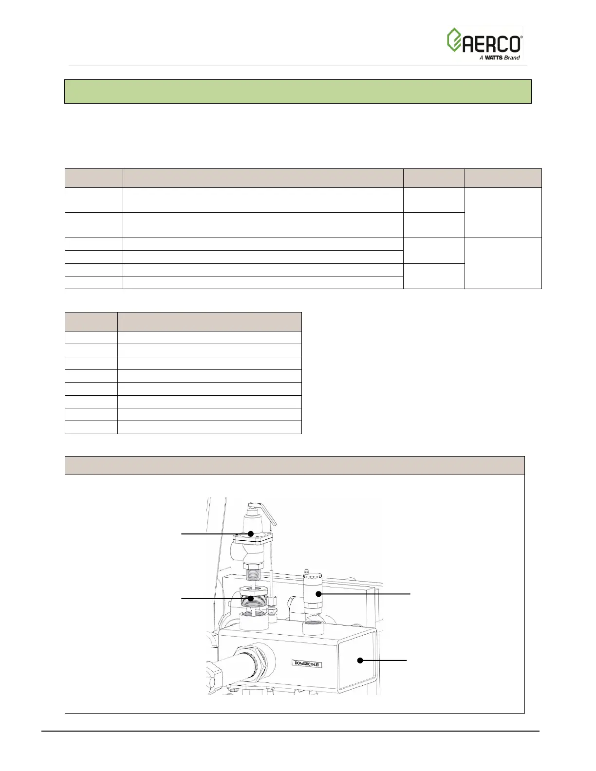
Complete the instructions below to install Relief Valve and Air Vent valves.
ADDITIONAL COMPONENT INSTALLATION Instructions
1. If you have a 150 PSI unit, install the parts as shown in Figure 2-9.
Figure 2-9. Relief Valve and Air Vent Valve Installation – 150 PSI – Exploded
1 ½” to ¾” Bushing
P/N 93521

 Loading...

