8. To permit Modbus control of the ECS/SP, refer to Table 2-2, below, and connect the
appropriate wire leads to the Temperature Controller terminals listed. Refer to the
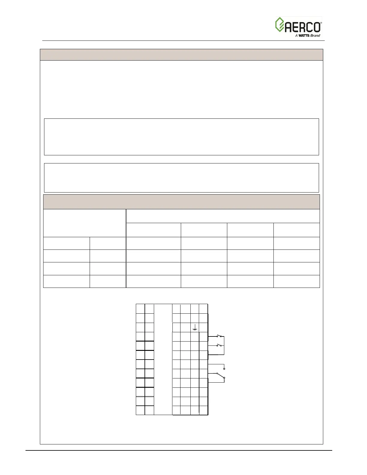
Temperature Controller (Eurotherm 2408) pinouts shown in Figure 2-8 to locate the
required terminals. Also, refer to Appendix A for instructions on how to change the
Temperature Controller Modbus address and for a listing of active Modbus data addresses
for the 2408 Controller. In addition, the Eurotherm documents referenced in this Appendix
provide additional communication information related to Modbus.
NOTE:
The complete wiring diagram for the SmartPlate Electronic Control System is provided in
Appendix B of this Instruction Manual. In addition, the wiring connections for Control Box
Terminal Blocks TB-1 and TB-2 are also provided for reference purposes.
NOTE:
AERCO recommends that shielded, twisted-pair cable be used for communication wiring.
Examples of suitable wiring are: Belden 9841, 8761, 3105A, or equivalent.

 Loading...

