EasyManuals Logo

Watts AERCO SmartPlate SP23 User Manual

Watts AERCO SmartPlate SP23
134 pages
To Next Page IconTo Next Page
To Previous Page IconTo Previous Page
Page #22 background imageLoading...
Page #22 background image
SmartPlate Installation, Operation & Maintenance Manual
CHAPTER 2 INSTALLATION
OMM-0069_0H SP-100 1/30/2020 Technical Support (800) 526-0288 Mon-Fri, 8 am - 5 pm EST Page 22 of 134
ADDITIONAL COMPONENT INSTALLATION Instructions
2. If you have a 200 PSI unit, install the parts as shown in Figure 2-10.
Figure 2-10. Relief Valve and Air Vent Valve Installation 200 PSI Exploded
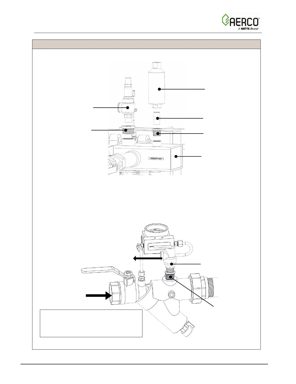
3. If the unit is being installed in New York City only (kits 58128-3 58128-6), in addition to
the steps above you must install a second Relief Valve (P/N 92111) in the Boiler Water
Intake Ball Valve/Strain combo, as shown in Figure 2-11. If the unit has 2 inch piping
(models SP-42, SP-61 or SP-113), you must include the 1” to ¾” bushing (P/N 93505).
Units with 1 ½” piping do not need this bushing.
Figure 2-11. Relief Valve Installation New York City Option
Relief Valve
P/N 92134-1
Bushing, 1 ½” to ¾”
P/N 93521
Air Vent Valve
P/N 92130
Nipple, ¾”
P/N 93451
Bushing, 1” to ¾
P/N 93505
Bushing, 1” to ¾
(2” Piping Only)
P/N 93505
Relief Valve
P/N 92111
Intake Mixing
Box
BOILER WATER
INLET
NOTE:
Rotate the Relief Valve so that the
outlet connection to the drain hose does
not interfere with other components
Relief Valve Outlet

Table of Contents

Questions and Answers:

Question and Answer IconNeed help?

Do you have a question about the Watts AERCO SmartPlate SP23 and is the answer not in the manual?

Watts AERCO SmartPlate SP23 Specifications

General IconGeneral
BrandWatts
ModelAERCO SmartPlate SP23
CategoryWater Heater
LanguageEnglish

Related product manuals