Do you have a question about the wattstopper DSW-301 and is the answer not in the manual?
Electrical voltage requirements for the DSW sensors.
Maximum load capacities for relay 1 across different voltages.
Maximum load capacities for relay 2 across different voltages.
Setting the duration before the sensor turns off after no motion.
Mode to reduce ON time for brief occupancy.
Mode for verifying sensor operation with short delays.
Setting the sensitivity of the Passive Infrared sensor.
Setting the sensitivity of the Ultrasonic sensor.
Operating frequency of the ultrasonic sensor.
Setting the threshold for ambient light detection.
Configuration for audible or visual warnings.
Indicates neutral wire availability for all models.
Support for connecting multiple sensors for common load control.
Recommended torque for terminal screws.
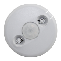
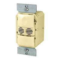
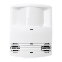
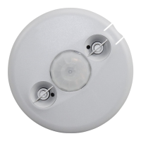
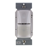
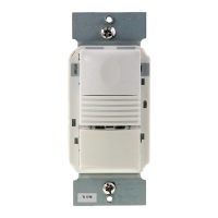
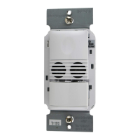
Combines PIR and ultrasonic sensors for enhanced detection.
Allows selection of Auto ON or Manual ON for load control.
Turns lights off after 3 minutes with minimal activity.
DSW-301 has one relay, DSW-302 has two relays.
Sensor detects ambient light to control load operation.
Explains how to set loads to Auto ON or Manual ON.
Test mode with a 5-sec delay, cancels after 10 min.
Shortens time delay for brief occupancy.
Default setting, suitable for most applications.
Reduces sensitivity by 50% for specific cases.
Unit beeps before load turns OFF.
No audible warnings are provided.
Both PIR and Ultrasonic required for initial and maintain occupancy.
PIR required for initial occupancy, either for maintain.
PIR required for initial and maintain occupancy.
Both PIR and Ultrasonic required for initial, maintain, and re-trigger.
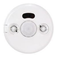
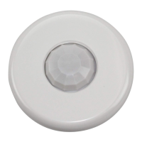
Describes the PIR sensor's lens and detection field.
How to mask the PIR sensor view to avoid unwanted areas.
Describes the ultrasonic sensor's transceivers and adjustability.
Procedure to remove and reinstall button caps for adjustments.
Steps to enable and set the light level control threshold.
Crucial safety warning to turn off power before installation.
First step in installation is power disconnection.
Wiring instructions for connecting leads to the sensor.
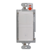
Mounting the sensor unit to the wall box.
Powering up the sensor after installation.
Final step to test and fine-tune sensor operation.
Final step of installing a cover plate.
Wiring diagram for single-relay models.
Wiring diagram for dual-relay models.
Wiring diagram for dual-circuit operation.
Sensors can be wired for common load control.
Rules for connecting multiple sensors for shared control.
Wiring example for DSW-301/301-347 up to 4 sensors.
Wiring example for DSW-302/302-347 up to 4 sensors.
Wiring example for dual-line, dual-load configurations.
Both sensors operate automatically based on occupancy.
One sensor controls automatically, the other requires manual ON.
Both sensors require manual ON operation.
DIP switch settings for time delay selection.
DIP switch setting to enable/disable Walk-Through mode.
DIP switch settings for PIR sensor sensitivity.
DIP switch settings for occupancy trigger options.
DIP switch setting for audible alerts.
DIP switch setting for Relay 1's ON mode (Manual/Auto).
DIP switch setting for Relay 2's ON mode (Manual/Auto).
Steps to resolve issues when lights don't turn ON but LED flashes.
Steps to resolve issues when lights don't turn ON and LED is off.
Steps to diagnose why lights are not turning off.
Solutions for false detection in unwanted areas.
Fixes for sensor not responding or LED being off.
Available colors for cover plates.
Details the five-year warranty for materials and workmanship.
Exclusions for consequential or indirect damages.
| Technology | Ultrasonic |
|---|---|
| Voltage | 120/277 VAC |
| Wire Size | 14-12 AWG |
| Operating Temperature | 32°F to 104°F (0°C to 40°C) |
| Material | Plastic |
| Color | White |
| Mounting | Wall |
| Time Delay | 30s-30m |
| Type | Wall Switch Occupancy Sensor |
| Product Type | Wall Switch Occupancy Sensor |
| Sensor Technology | Passive Infrared (PIR) and Ultrasonic |
| Load Rating | 800W @ 120V, 1200W @ 277V |