Do you have a question about the wattstopper DT-300 and is the answer not in the manual?
Connects the low voltage wires from the power pack to the sensor terminals.
Connects the power pack to the sensor for occupancy-controlled lighting.
Instructions for adding a manual switch for occupancy control.
Details for connecting the isolated relay for external interfacing.
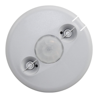
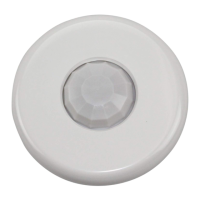
Instructions for mounting the sensor directly onto a ceiling surface.
Instructions for mounting the sensor using an octagonal junction box.
Procedure for testing sensor functionality and initial setup.
Configuration of initial occupancy detection logic using DIP switches.
Setting the time delay for lights to remain on after occupancy.
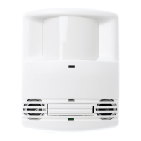
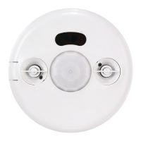
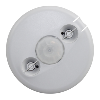
Control and status indication via PIR and Ultrasonic LEDs.
Adjustment of Passive Infrared sensor detection range.
Steps to diagnose when no LEDs are active on the sensor.
Diagnosing issues when the PIR activity LED is not functioning.
Diagnosing issues when the Ultrasonic activity LED is not functioning.
Troubleshooting when the Ultrasonic LED remains constantly lit.
Diagnosing problems indicated by both PIR and Ultrasonic LEDs flashing.
Reducing ultrasonic sensitivity when the green LED flashes.
Checking manual switch connection when specific LEDs behave unexpectedly.
Reducing PIR sensitivity by adjusting DIP switch 8.
Steps to troubleshoot when lights fail to turn off automatically.
| Technology | Passive Infrared (PIR) |
|---|---|
| Sensitivity Adjustment | Yes |
| Ambient Light Level Adjustment | Yes |
| Type | Occupancy Sensor |
| Time Delay | 30 seconds to 30 minutes |
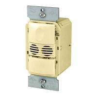
| Mounting | Wall or ceiling mount |
| Operating Temperature | 32°F to 122°F (0°C to 50°C) |
| Agency Listings | UL |