Quick Start Guide
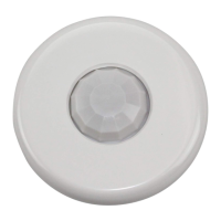
SENSOR PLACEMENT 10’ MAX. HEIGHT
Strong air
supply
6’
Sensor
Mount sensor at least 6’ away from hot air supply.
void obstacles that block sensor’s line-of-sight.
Pendant
xture
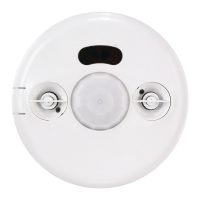
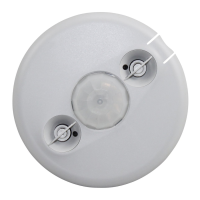
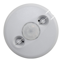
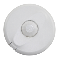
LMDC-100
Digital Lighting Management
Dual Technology Ceiling Mount
Occupancy Sensor
Voltage ................................................................................24VDC
Current Consumption .......................................................... 20mA
Power Supply .............. Watt Stopper/Legrand Room Controllers
Connection to the DLM Local Network ...................2 RJ-45 ports
DLM Local Network Characteristics:
Provides low voltage power over Cat 5e cable (LMRJ).
Supports up to 24 communicating devices, including 4
LMRC-10x or LMPL-101 max per each DLM Local Network.
Free topology up to 1,000ft of low voltage cable.
Environment ................................................. For Indoor Use Only
Operating Temperature ....................32° to 131°F (0° to 55°C)
Storage Temperature ...................... 23° to 176°F (-5° to 80°C)
Relative Humidity ...........................5 to 95% (non condensing)
Patent Pending
Sensor
25'
5
25 ft
(7.62m)
25 ft x 25 ft
(7.62m x 7.62m)
PIR
Coverage
Ultrasonic
Coverage
COVERAGE PATTERN
The LMDC-100 provides a 360° coverage pattern. The
coverage shown represents walking motion at a mounting
height of 10 feet.
Line
Voltage
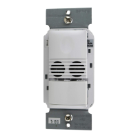
Room
Controller
J-Boxes
Daylight Sensor
SwitchSwitch
Corner Mount
Sensor
Ceiling Mount
Sensor
DLM Local Network
Low Voltage
LMRJ Cables
Loads
2
1
Line/Hot
Black wire
Neutral
White wire
Red wire
to Load A (1)
Yellow wire
to Load B (2)
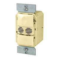
LMRC
102
Room
Controller
J Box
Ceiling Mount
Occupancy
Sensor
Switch
To
Load
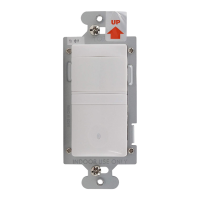
THIS UNIT IS PRESET FOR PLUG n’ GO™
OPERATION, ADJUSTMENT IS OPTIONAL.
For full operational details, adjustment and more
features of the product, see the DLM System
Installation Guide provided with the LMRC-102 and
also available at
www.wattstopper.com
CONNECTIVITY
The illustrations below show examples of free-topology wiring. The LMDC-100
communicates to all other Digital Lighting Management devices connected to the low
voltage DLM Local Network, regardless of their position on the DLM Local Network.
INSTALLATION SHALL BE
IN ACCORDANCE WITH ALL
APPLICABLE REGULATIONS,
LOCAL AND NEC CODES.
Intended for Listed Class
2 DLM Devices.
For Class 2 DLM devices -
To be connected to a Class
2 power source only.
For Class 2 Device Wiring Only –
Do Not Reclassify and Install as
Class 1, or Power and Lighting
Wiring.
Wire connections shall be rated
suitable for the wire size (lead
and building wiring) employed.