16
Please Do Not Return This Product To The Store. Contact your local Wayne-Dalton dealer. To find your local Wayne-Dalton dealer, refer to your
local yellow pages/business listings or go to the Find a Dealer section online at www.wayne-dalton.com
Tools Needed:
Top Brackets
Power Drill
7/16” Socket
Driver
7
TOP BRACKET SLIDE
(2) 1/4”- 20
FLANGE HEX
NUTS
ROLLER
TOP BRACKET SLIDE
TOP SECTION
TOP SECTION
(2) 1/4”- 20 x 5/8”
CARRIAGE BOLTS
2ND
SET
1ST
SET
3RD
SET
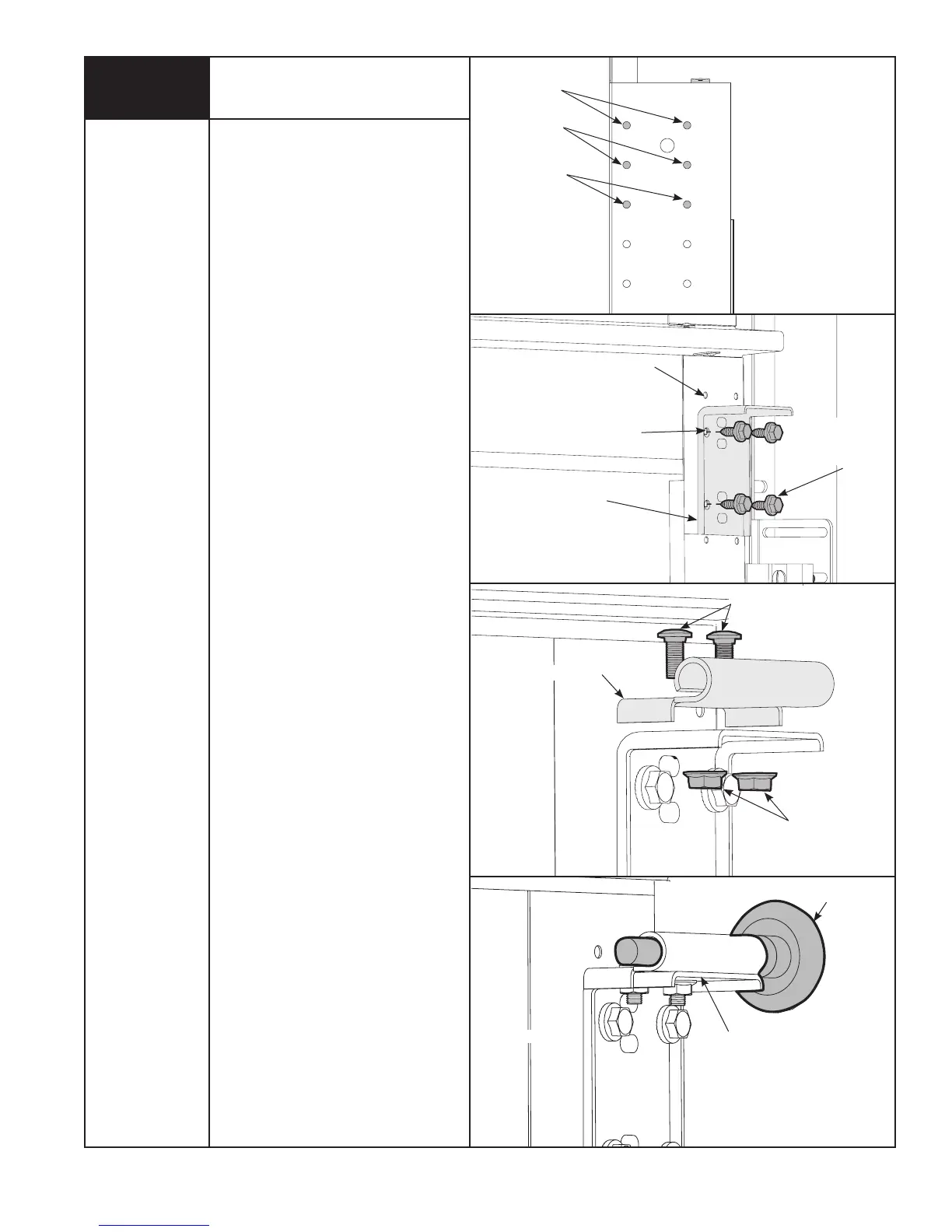
NOTE: This step may be pre-assembled
on some models.
To install the L-shaped top brackets,
align the top holes in the top bracket
base with:
a) the second set of holes in the endstile
for 14” radius track.
b) the first set of holes in the endstile for
10” & 12” radius track.
Fasten using (4) 1/4”- 14 x 5/8” self
tapping screws.
Secure the top bracket slide to the
bracket base using (2) 1/4”- 20 x 5/8”
carriage bolts and (2) 1/4”-20 flange
hex nuts.
The top bracket slide will be tightened
and adjusted in Step 13. Insert rollers
into top bracket slide. Repeat for other
side.
(4) 1/4” - 14 x 5/8”
SELF TAPPING
SCREWS
TOP BRACKET BASE
1ST SET
(10” & 12” RADIUS)
2ND SET
(14” RADIUS)
TOP SECTION