17
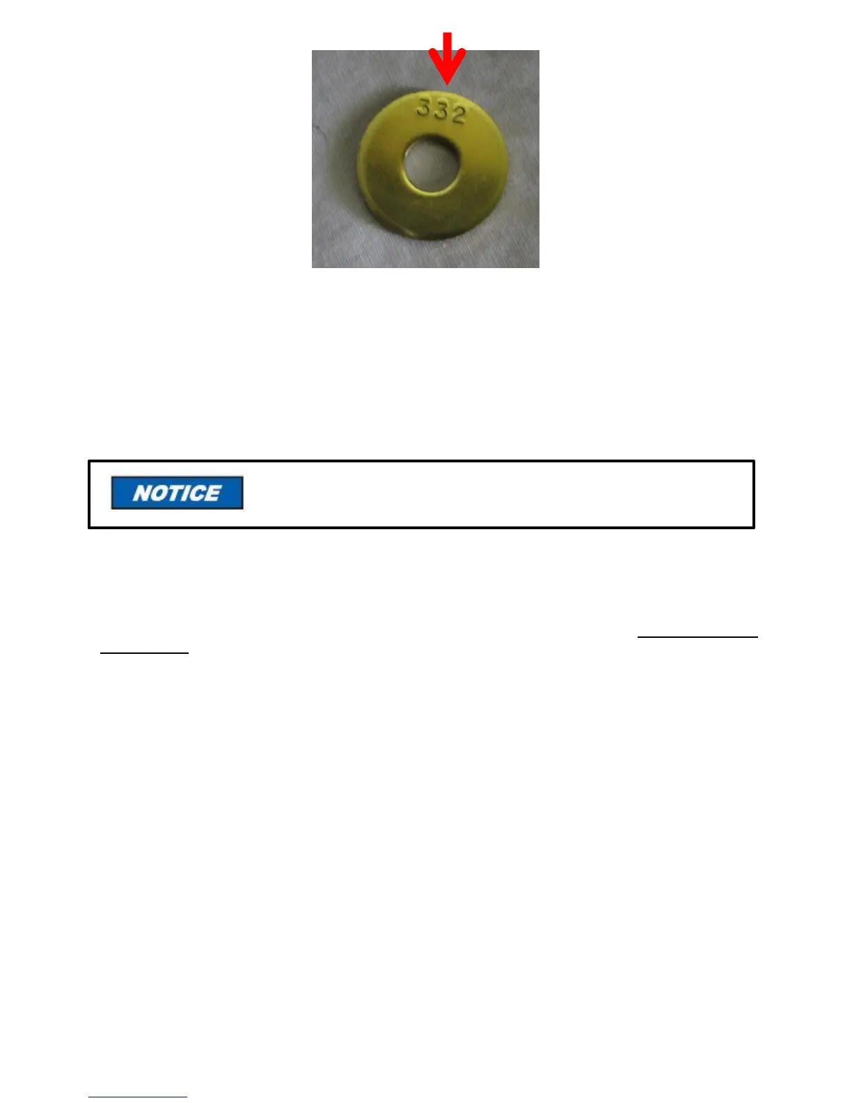
Figure 15: HSG Orifice
Install the new orifice in manifold, reinstall spring and cap with gasket in the manifold. The orifice kit
included with conversion burners also contains gas identification labels. When changing from one gas to
another, locate the gas identification label on the burner and if necessary, place the proper label from the
kit over the label on the burner. The burner is now ready to be connected to the gas supply piping; see
instructions in next section.
INSPECTION AND SIZING OF GAS PIPING
A sediment trap or drip leg must be installed in the supply line to the burner. A union shall be installed in
the gas line upstream from the control manifold and downstream from the sediment trap or drip leg (See
Figure 16). A 1/8” NPT plugged tapping port accessible for test gauge connection shall be installed
immediately upstream of the gas supply connection for the purpose of determining the gas supply pressure
to the burner. A manual shutoff valve shall be installed in the gas supply line external to the appliance (See
Figure 16). If the gas supply pressure exceeds the 14” w.c. (3.5 kPa) maximum, an intermediate main
gas regulator must be installed ahead of the main gas manual shutoff valve shown in Figure 16.
All piping must comply with local codes and ordinances or the
National Fuel Gas Code ANSI Z223.1/NFPA No. 54.