11
5. Once the fuel unit is primed (no signs of air in oil bleeder port discharge), close the bleed port. Burner will
ignite.
6. When flame is established, make a temporary air adjustment to the slotted air band for a visually clean combus-
tion smoke observed from the appliance vent. Allow the appliance to warm up approximately five minutes or until
the water temperature reaches that recommended by the cleaning equipment manufacture.
7. Adjust the slotted air band shutter until a #1 to #2 smoke (Shell Bacharach scale) is obtained at the appliance
vent.
8. Check CO
2
(carbon dioxide) and/or O
2
(oxygen) percentages and smoke in the flue gas at the appliance vent. In
general, CO
2
readings should be in the 10% to 12% range and O
2
readings in the 7.4% to 4.7% range.
9. Once the desired combustion results are attained, securely tighten slotted air band screw and check that controls
on the appliance are adjusted per the cleaning equipment manufactures instruction sheets. Remove oil pressure
and vacuum gages from the fuel unit and reinstall pipe plug fittings.
10. Check burner lighting with hot chamber, then allow burner and appliance to sufficiently cool. Then check burner
lighting with a cold chamber.
SUGGESTION: all new installations should be reinspected after one or two weeks of normal operation.
MAINTENANCE
OILING MOTOR – The MSR_DC oil burner is provided with a ball bearing shaft motor. Ball-bearing motors do not
require oiling under normal service conditions.
FILTER – The oil filter cartridge should be replaced, or sediment cleaned, periodically so the fuel oil will not become
contaminated and plug up the fuel pump and nozzle of oil burner.
NOZZLE – The nozzle should be changed at least once each year or twice a year if the cleaning equipment is used
daily through the year and should poor combustion occur. Replace with the proper nozzle.
COMPONENTS – If for any reason any of the burner parts have to be replaced, always use parts recommended by
the manufacturer. Specify part numbers and description when ordering. (IN ALL COMMUNICATIONS STATE BURN-
ER MODEL AND SIX DIGIT SPECIFICATION NUMBER).
ELECTRODE SETTINGS – This is very important for reliable ignition of the oil; check these once a year in accor-
dance with the instructions provided in this manual. Replace electrodes if worn excessively or if porcelain insulator
is oil soaked or cracked (See Figure 1).
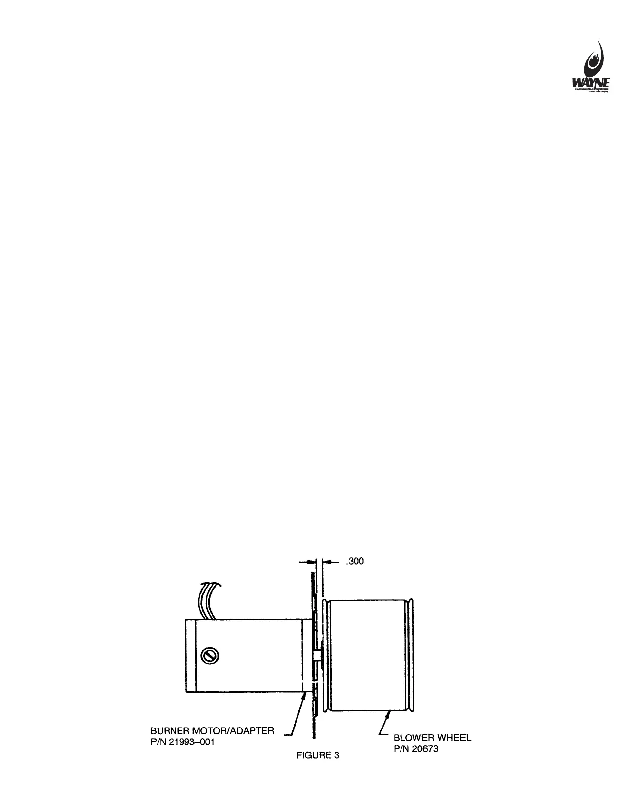
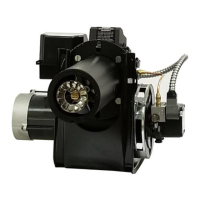
FAN & BLOWER HOUSING – This must be kept clean, free of dirt and lint; open transformer to check fan blades
from above. Be sure the electric power is off on burner when the transformer is opened up for this inspection. Should
the blower wheel be removed for replacement or cleaning, reinstall as shown in figure 3.