34 920749 Rev G 7/2014
E/G6101D/G6101D
18 Blue
Junction Box
Breakers
To Subm.
Starter Relay
L1
N
Pump Feed
Return
Subm Feed
Red
Y/G
Red
Nickel-
Plated
Valve
18 Orange
18 White
14 Red
NC
NC
NO
C
14 Black
Ground Screw
Reset
Reset
Motor
CNO
Handle
C
NO
NC
NC
CNONO C
NC
NC
NO
C
Handle
NO C
Reset
Motor
Reset
Ground Screw
14 Black
C
NO
NC
NC
14 Red
18 White
18 Orange
Valve
Fast
Slow
Red
Black
Yellow
Subm Feed
Return
Pump Feed
N
L1
To Subm.
Starter Relay
Breaker
Junction Box
18 Blue
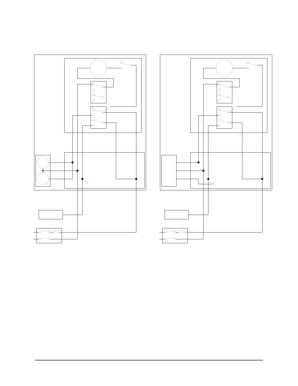
Wiring Diagram: G6101D Single Remote Dispenser
Notes:
1. All equipment to be installed in accordance with all applicable local, state, and federal codes, including, but not
limited to, the National Electrical Code (NFPA 70), NFPA 30, and the Automotive and Marine Service Station
Code (NFPA 30A).
2. For wiring connections, use wires rated at least 90ºC, 600V, Gas & Oil Resistant.
3. See the wire size chart for proper gauge of the wires.
4. A submersible starter relay should be used for the control of the submersible pump.
5. Reset Complete – When connecting to a fuel management system, a signal indicating when the reset process
is complete and the dispenser is ready to dispense fuel may be required. Use the Orange wire for this signal.
The signal will be 115VAC for 115VAC units (int’l - 230VAC). The signal will return to 0VAC when the handle is
turned off.
6. For full details of interconnections, see Section 3.3.
 Loading...