DOC P/N 5001063A KIT P/N 5001062B Printed in USA Webasto Product N.A., Inc.
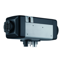
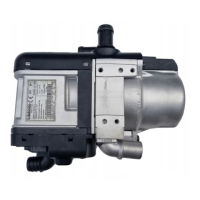
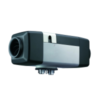
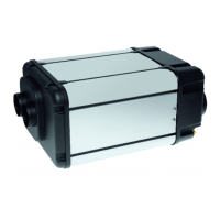
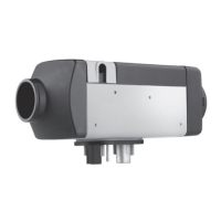
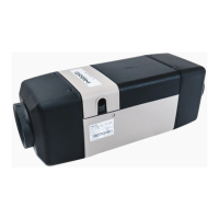
BlueHeat Coolant Heater
Thermo Top
Legend
1BlueHeat Coolant Heater, Exhaust Tube, and Combustion Air Intake Silencer
2 Fuse Holder, Relays and Resistor Assembly
3Timer Control
4Fuel Pump
Special Tools
– Hose Clamping pliers
– Torque Wrench
Table of Contents
4
2
3
1
VW Passat
Beginning Model Year: 2005
Special instructions for these models
Part locations may differ slightly dependent on
the vehicle model.
Foreword
Parts List 3
Vehicle Information 3
Scope and Purpose 3
Symbol Identification 4
General References 5
Preparation 5
Heater Installation Site 5
Installation
Electrical - Overview 6
Electrical Harness 7
Timer Installation 8
Integration into the Blower System 8
3-Relay HVAC Harness Connections 9
Heater Preparation/Installation 10
Integration into the Fuel System 11
Standpipe Installation 11
Fuel Pump Installation 12
Fuel Line and Electrical Harness Routing 13
Integration into the Coolant System 15
Webasto Heater Hose Integration Point 16
Webasto Heater Outlet Hose Installation 16
Webasto Heater Inlet Hose Installation 16
Heater Mounting Site 17
Fuel Line Connection at Heater 17
Air Intake Silencer Installation 17
Exhaust System Installation 18
Power and GroundConnections 18
Fuse Tap Connection - Relay K-1 18
Final Inspection, Initial Start-up and Concluding
Work 19
Heater Lockout Reset Procedure 20
Electrical Harness Schematic - Part 1 21
Electrical Harness Schematic - Part 2 22
Heater Plumbing Schematic - Inline Method 23