VW Passat
9
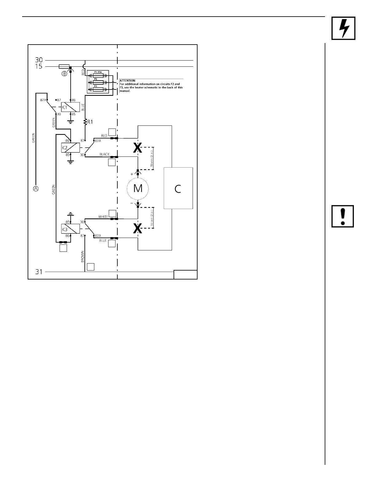
3-Relay HVAC Harness Connections
NOTE:
It is permissible to cut excess length from
Webasto HVAC wiring harnesses to fit the
application.
Cut motor wires where indicated by
“
X
”
– (1) Chassis ground
– (2) Splice green wire to green wire
– (3) Strip and crimp red wire to (BLK/GN)
controller side blower control positive
wire
– (4) Strip and crimp black wire to (BLK/GN)
motor side blower control positive wire
– (5) Strip and crimp white wire to (BROWN)
motor side blower control negative wire
– (6) Strip and crimp blue wire to (BROWN)
controller side blower control negative
wire
CAUTION
Check your wiring! Ensure that all
connections have been done in accordance
with the wiring diagram shown (Fig. 10).
Sensitive electronic controls can be
damaged if wired incorrectly!
Secure HVAC blower control wiring to
vehicle structures with nylon wire ties.
(Image not available)
NOTE:
Complete heater harness schematics are
included on page 22 and 23 of this manual.
Legend for Figure 10
A From Webasto Heater X1
B 12 VDC Ignition ‘On’ Fuse Tap
C HVAC Control Module
M HVAC Blower Motor
X Cut wire at 50 mm (2 in.) from motor
F1 Fuse - Blower Circuit 25 Amp.
K1 Relay - Ignition ‘On’ Interrupt
K2 Relay - Positive Side of Blower Motor Circuit
K3 Relay - Negative Side of Blower Motor Circuit
R1 Resistor - Blower Speed Control
30 Battery Positive (Constant Power)
15 Ignition (Switched Power)
31 Battery Negative (Chassis Ground)
2
1
6
5
4
3
Webasto Vehicle
Fig. 10
BROWN
BROWN
BLK/GN
BLK/GN