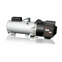
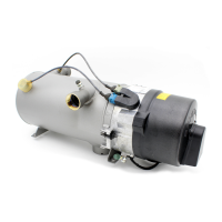
DBW 2010 / 2016 Electrical connections
43
10 Electrical connections
10.1. Heater connection
IMPORTANT HIGH VOLTAGE:
Danger of death. Disconnect the plug connection to the vehicle before
you open the heater.
The electrical connection of the heaters is made as shown in Figure 11
(DBW 2010) or Figure 12 (DBW 2016):
System circuit for DBW 2010 / 2016 with SG 1553 control unit and switch.
Connections of the heaters differing from those of the standard variant
(Figures 11 / 12) are shown in Figure 13 (heater variants and plug
assignments), Figures 14 / 15 (nozzle block preheating system) and
Figure 16 (timer).
Use the specified cable cross-sections.
Connect the negative and positive terminals of the heater controller
directly to the battery.
10.2. Connecting the controls
The heater can be switched on and off using the following Webasto
controls:
– Switch, see automatic circuit diagram Figures 11 to 15
– Timer, see circuit diagram Figure 16
1303560C_DBW 2010 EA_degbfr.book Page 43 Tuesday, March 5, 2013 9:05 AM
 Loading...