9 Wiring diagrams
r·
I
I
I
l
1©
~L-
.A
•
..
~
'
·•·
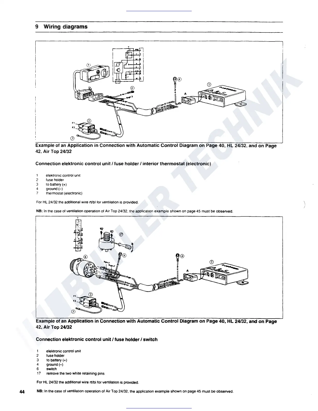
Example of
an
Application
in
Connection
with
Automatic
Control
Diagram
on
Page 40,
HL
24/32,
and
on
Page
42,
Air
Top 24/32
Connection elektronic
control
unit/
fuse
holder/
interior
thermostat
(electronic)
1 elektronic control
urnt
2 fuse holder
3 to battery(+)
4 ground(-)
7 thermostat (electronic)
For
HL
24/32
the
additional wire rt/bi
for
ventilation
is
provided.
NB:
In
the
case
of
ventilation operation
of
Air
Top
24/32.
the
apphcauon example shown
on
page
45
must be observed.
~©
f
CD
• A
Example of
an
Application in Connection with Automatic Control Diagram on Page 40, HL 24/32, and on Page
42,
Air
Top
24/32
Connection elektronic control
unit/
fuse
holder/
switch
1 elektronic control unit
2 fuse holder
3
to
battery(+)
4 ground(-)
6 switch
17
remove
the
two white retaining pins
For
Hl
24/32
the
additional wire rt/bi for ventilation
is
provided.
44
NB:
In
the
case
of
ventilation operation
of
Air Top 24/32, the application example shown
on
page 45 must be observed.
 Loading...