Wiring diagrams 9
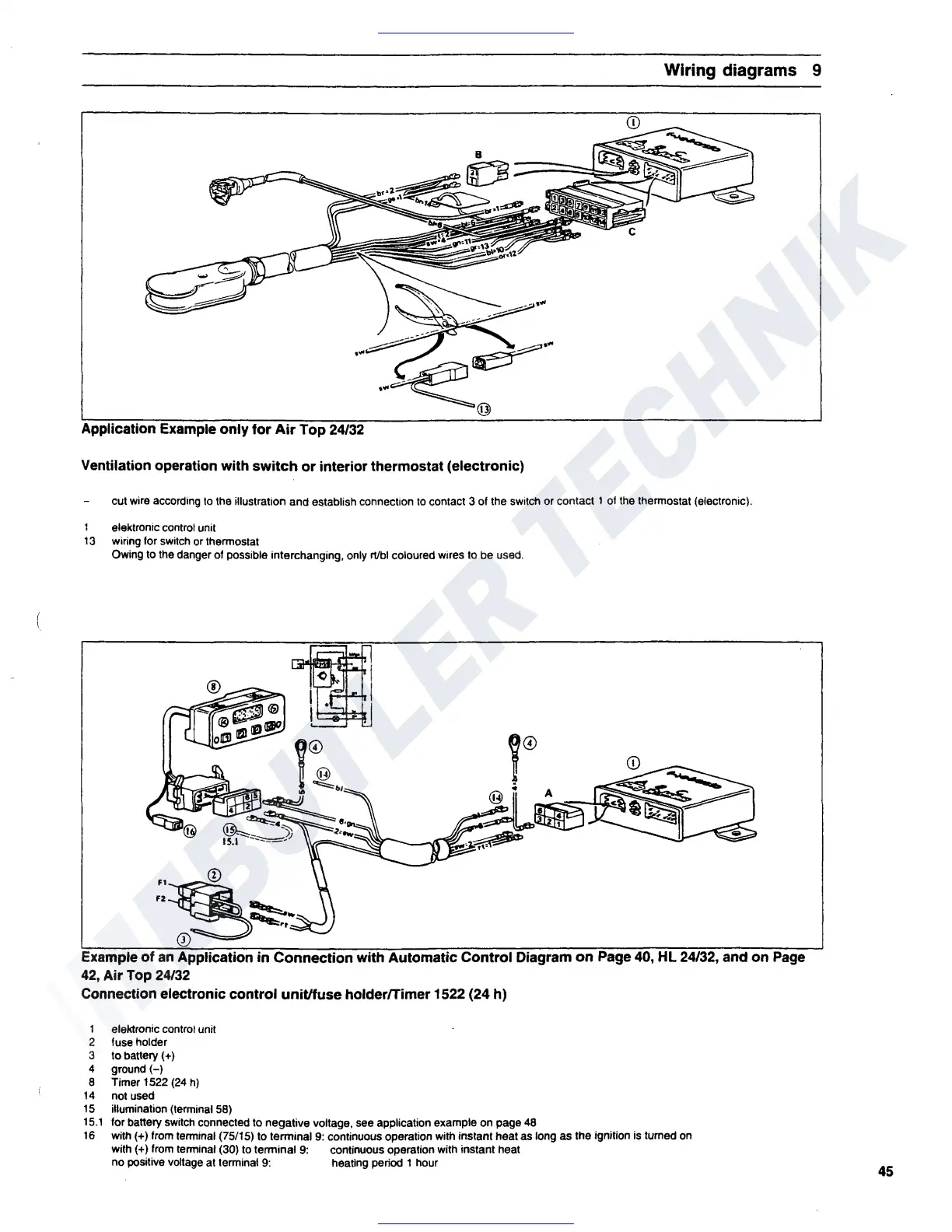
Application Example only
for
Air
Top
24/32
Ventilation operation with
switch
or
interior thermostat (electronic)
cut wire according lo the illustration and ei;tablish connection
to
contact 3 of the switch or contact 1 of the thermostat (electronic).
elektronic control unit
13
wiring for switch or thermostat
Owing to the danger of possible interchanging, only
rt/bi coloured wires to be used.
~~~
~
t©
..
-4
---
-)
15.1
-=-
Example
of
an
Application
in
Connection with Automatic Control Diagram
on
Page
40,
HL 24/32, and on Page
42, Air
Top
24/32
Connection electronic control unit/fuse holder/Timer 1522 (24 h)
1 eleklronic control unit
2 fuse holder
3
to
battery(+)
4 ground(-)
8 Timer 1522
(24
h)
14
not used
15
illumination (terminal 58)
15.1
for battery switch connected to negative voltage, see application example on page
48
16
with(+) from terminal (75/15) to terminal
9:
continuous operation with instant heat as long as the ignition is turned on
with(+)
from
terminal (30)
to
terminal
9:
continuous operation with instant heat
no positive voltage at terminal
9:
heating period 1 hour
45
 Loading...