Fuel Installation
Fuel Supply
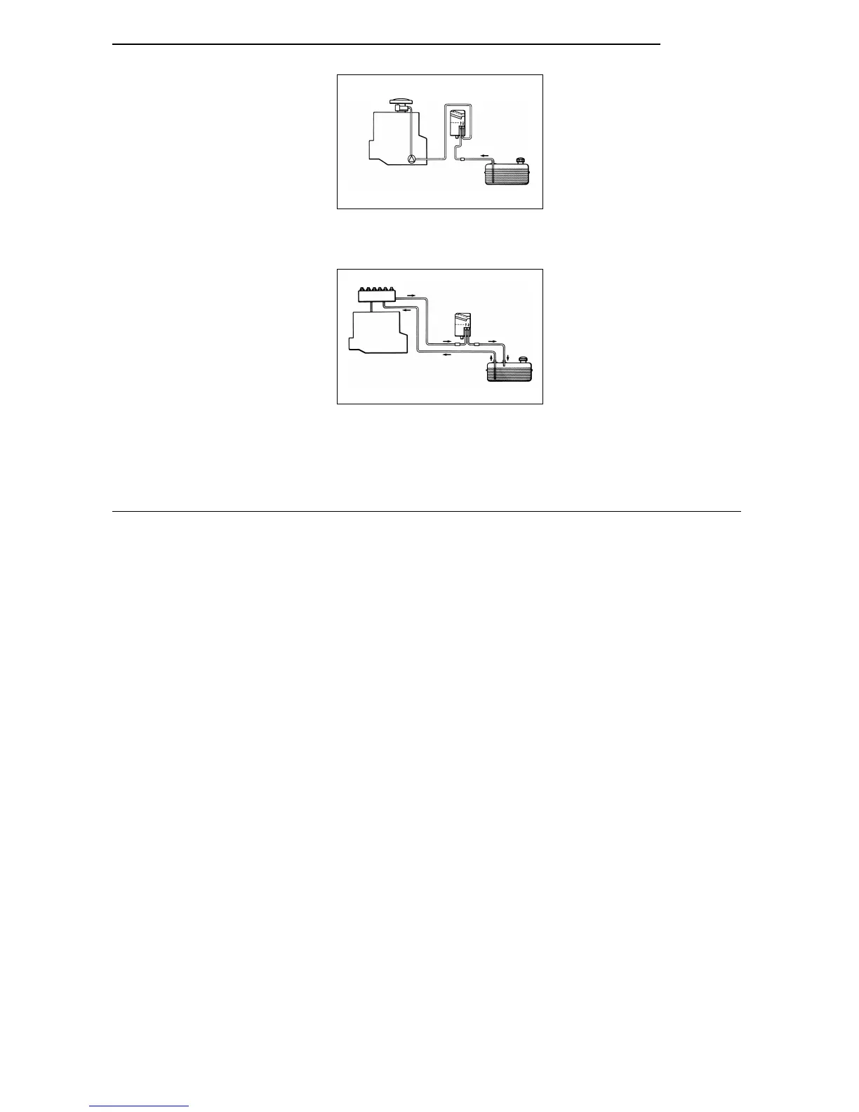
In the case of carburetor or injection engines equipped
with return line, the heater’s fuel supply circuit must be inte-
grated in the return line as shown in Fig. 8.
The direction arrows provided on the heater must be ob-
served.
In the case of carburettor engines without return line, the
fuel supply circuit of the heater must be integrated in the
flow line between vehicle fuel tank and pump as shown in
Fig. 7.
ANNOTATION
A fuel flow line can usually be identified by the in-line fuel
filter.
NOTE:
If the fuel system of the vehicle is equipped with a degass-
ing device, fuel extraction is to take place upstream of
same.
Fuel Lines
Only the special hoses supplied with the heater by We-
basto must be used as fuel lines between fuel connections
and heater. When using hoses, the joints are to be se-
cured using hose clamps. To prevent any sagging the fuel
line must be secured with clips.
Prior to cutting the fuel line open it must be clamped off or
a suitable vessel placed underneath the pipe.
Any fuel that may have leaked is to be removed from the
engine or heater prior to starting up the vehicle or heater
The fuel lines - not cut to length as yet - are to be con-
nected to the vehicle’s return line.
Keeping slack to a minimum, they are then to be routed
along any obstructing vehicle parts up to the fuel connec-
tions of the heater and the length thus obtained is to be
marked.
The fuel lines are to be cut off 35 cm longer than marked.
The excess length of the fuel lines of 35 cm is to be dis-
tributed evenly. The fuel lines are to be so fastened that
they will not be damaged by vehicle parts that may come
in contact with them.
The lines must be mounted in such a way that they are pro-
tected from mechanical damage (e.g. stones) and thermal
influence (e.g. exhaust pipe). If the fuel line is damaged
there is a danger of fire.
NOTE:
The hose clamps are to be tightened to a torque of 1.0 +
0.4 Nm.
Combustion Air Supply
Combustion air is to be drawn in from a location as cool as
possible and splash-proof via a combustion air line.
The combustion air line which is contained in the installa-
tion kit must not be extended.
It may be shortened to a min. of 500 mm.
The combustion air line may feature several bends (total of
270°, smallest bending radius 50 mm).
NOTE:
The combustion air line consists of an inside and outside
part.
Shorten combustion air line only at the end that is not pro-
vided with a fastening clip.
fuel pump
engine
carburator
Fig. 7: Fuel Supply Circuit in the Single Line Sys-
tem (Carburetor Engine without Return Line)
“Inline Integration between Pump and Car-
buretor”
engine
injection system
flow pipe
return pipe
Fig. 8: Fuel Supply Circuit in the Double Line Sys-
tem (Carburetor or Injection Motor with Re-
turn Pipe) “Inline Integration in Return Flow”
Thermo Top
21
 Loading...


