Page 13 Burner Mounting CriteriaSC Manual
E. BURNER MOUNTING CRITERIA
It is of vital importance that the burner be properly mounted to the boiler or appliance being red. Improper mounting
can cause leakage of the hot gases back around the burner head resulting in warpage and deterioration. The follow-
ing illustrations show the proper way the burner must be installed to validate warranty conditions.
A
B
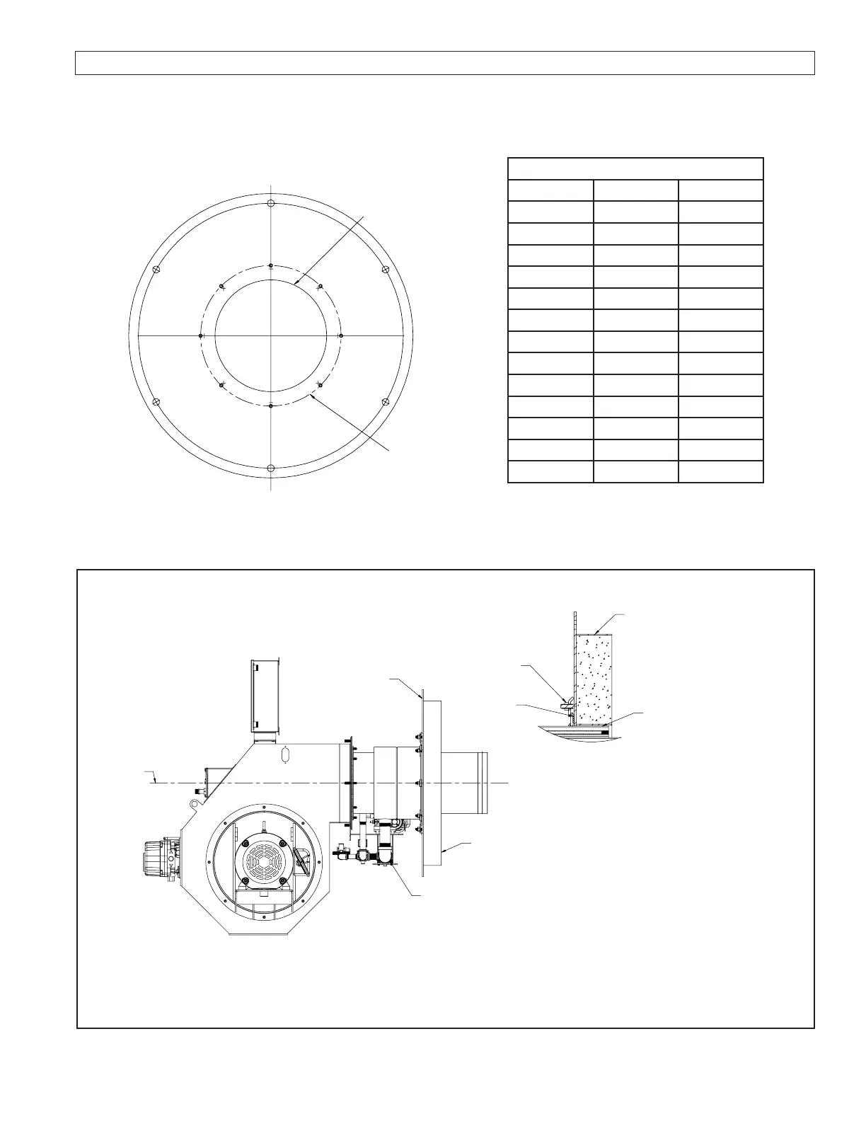
TYPICAL SC BURNER REFRACTORY FRONTPLATE
Dimensions - Inches
MODEL DIM. A DIM. B
SC8 9.25” 14.00”
SC10 11.25” 16.00”
SC12 13.25” 17.00”
SC12.3 13.56” 19.00”
SC13 15.00” 19.00”
SC13.8 15.00” 19.00”
SC14 15.25” 19.00”
SC15 17.00” 20.50”
SC15.8 17.00” 20.50”
SC16 17.25” 20.50”
SC18 19.25” 22.50”
SC20 21.25” 24.50”
SC24 25.25” 28.50”
Figure E-1
Refractory Dimension
Contact Webster for more detailed
refractory drawings.
Figure E-2
Burner Mounting Instruction
BURNER MUST
BE LEVEL
REFRACTORY
FRONT PLATE
IF GAP IS OVER 3/16”
WRAP BURNER NOSE WITH
HIGH TEMPERATURE
CERAMIC INSULATION ROPE
FILL VOIDS BETWEEN FRONT
PLATE AND VESSEL WITH
CERAMIC BLANKET 4” DEEP
OR AS DEFINED BY VESSEL
MANUFACTURER
THIS SURFACE MUST
BE SEALED AGAINST
THE VESSEL. CHECK
VESSEL MOUNTING
REQUIREMENTS.
THIS SURFACE
MUST BE SEALED
AGAINST THE
VESSEL. CHECK VESSEL
MOUNTING
REQUIREMENTS.
ATTACHMENT TO VESSEL VARIES WITH MANUFACTURE.
(FOLLOW VESSEL MANUFACTURER’S RECOMMENDATION)
THE GAS PIPING FROM THE BURNER TO THE
TRAIN SHOULD HAVE AS FEW ELBOWS AS
POSSIBLE TO REDUCE PRESSURE DROP.
 Loading...
