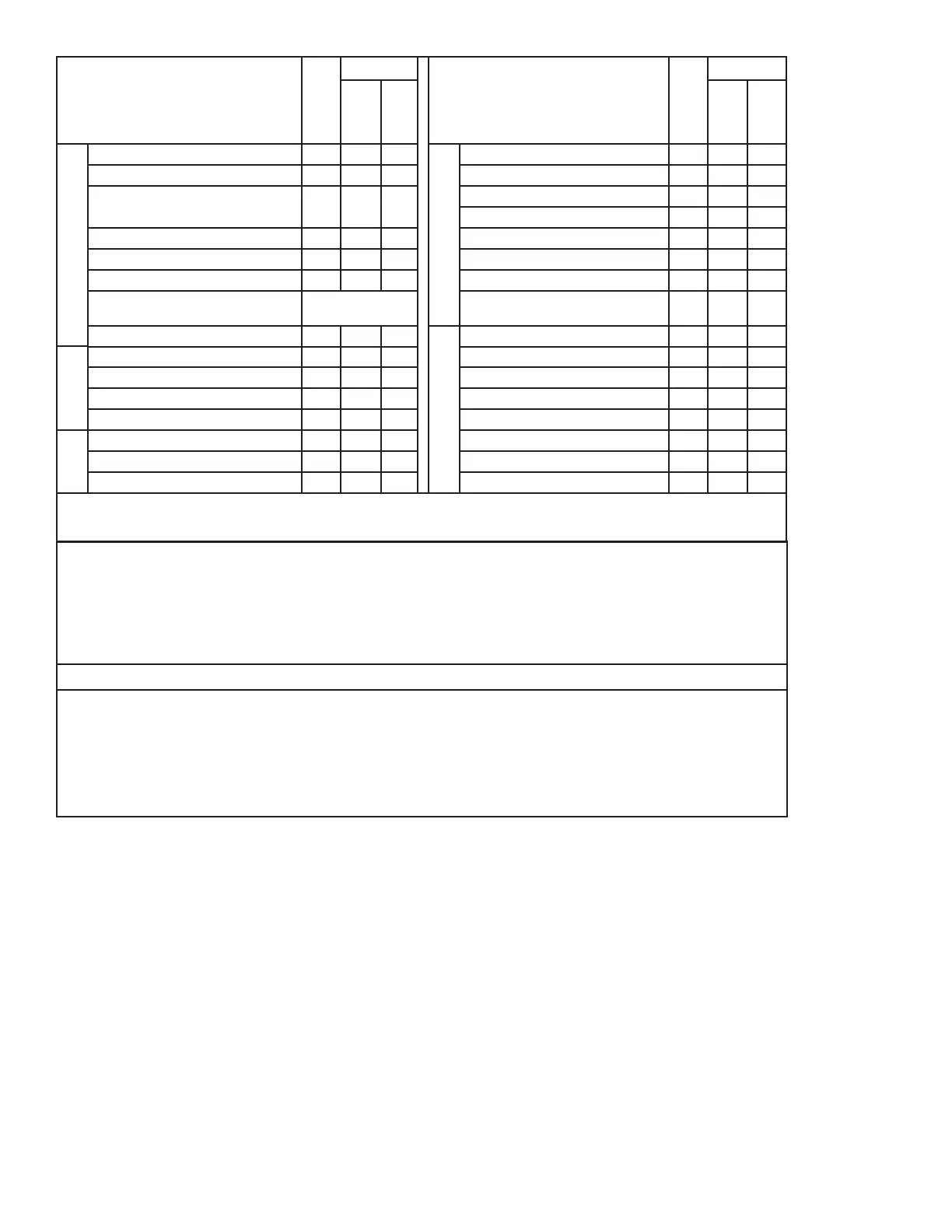
STANDARD UL EQUIPMENT
AND IMPORTANT OPTIONS (1)
STANDARD UL EQUIPMENT
AND IMPORTANT OPTIONS
General
Motor, Fan and Air Inlet Control X X
Gas Fuel
Main Manual Shutoff Valve X
Air Flow Switch (also with oil systems using remote
pump)
X X Main Safety Shutoff Valve X
Burner Mounted Control Panel, Switch and Indicator
Lights (2)
X X Second Safety Shutoff Valve X
Flame Safety Control X X Main Gas Regulator X
Ultra Violet Scanner X X Gas Checking Valve X
Motor Controller (single phase voltage)
Fuel Selector Switch
High and Low Gas Pressure Switches (st’d
over 2500 MBH)
Opt.
Ignition
Proven Gas Pilot Ignition
X X
Optional
Inverted Housing
Pilot Solenoid Gas Valve
X X Alternate Control Cabinet Positioning
Pilot Gas Regulator & Manual Valve X X Remote Control Panel
Pilot Gas Ignition Transformer X X
Direct Spark Oil Ignition X X
Direct Spark Oil Ignition Transformer X X
1. The conguration of each unit will vary with specic job requirements such as input rating, electrical specication and special agency approval
codes. The above chart shows those items standard to a basic burner plus a few options that may be added.
2. Indicator lights are “Power On”, “Call for Heat”, ”Fuel On” and ”Flame Fail” for hard wired panels. “Alarm”, “Low Water”, “Power”, “Call for
Heat”, “Ignition On”, and “Fuel On” for circuit board light panels.
?. Larger motors may be required for single phase or 208 volts
The above maximum ratings are based on 0 furnace pressure, an altitude of 1000 feet, 90
o
F air temperature and 60 HZ electrical
supply. Use the following corrections for higher temperatures and altitude. Capacity decreases by 17% for 50 Hertz.
Capacity decreases by 4% for each 1000 feet above 1000 foot altitude.
Capacity decreases by 5% for each 1 inch of furnace pressure.
Capacity decreases by 2% for each 10
o
F increase in air temperature over 90
o
F.
Gas input ratings based on 1000 BTU/cu ft. and 0.64 specic gravity. Sizes and pressure will vary with gas.
Essential Ordering Information and Data:
Power Supply - Conrm 120-60-1 for control circuit and electrical supply for burner motor(s) (voltage, frequency and phase).
Describe Boiler or Heater to be Fired - Including the manufacturer, model number, furnace pressure and furnace size.
Firing Rate - Dene ring rates in MBH for gas. Fuel to be Burned - Type of gas, including the BTU value.
Approval Agency - UL, FM, IRI (GE GAP), CSD-1, NFPA, Mil spec and local codes, if applicable.
Flame Safety Control Preferred - Honeywell or Fireye controls.
Gas Train Components Preferred - ASCO/ITT, Honeywell or Landis
Control System - ON-OFF, Low Fire Start, Low-High-Low, Modulation, Posi-Control
Required Options - Mounting plate, limit controls, etc.
Model SC - Specication Data (2,400 MBH - 28,800 MBH Input)
Power Supply: Conrm 120-60-1 for control circuit and electrical supply for burner motor(s) (voltage, frequency and phase).
Describe Boiler or Heater to be Fired: Including the manufacturer, model number, furnace pressure and furnace size. Firing Rate: Dene ring rates
in MBH for gas. Fuel to be Burned: Type of gas and/or oil, including the BTU value. Approval Agency: UL, FM, IRI (GE GAP), CSD-1, NFPA, Mil spec
and local codes, if applicable. Flame Safety Control Preferred: Honeywell, Fireye or Siemens controls. Gas Train Components Preferred: ASCO/
ITT, Honeywell or Landis Control System - Modulation, Posi-Control Required Options - Mounting plate, limiting controls, etc.
Model SC - Specication Data
Page 6 Specication DataSC Manual
Model SC - Specication Data (2,400 MBH - 28,800 MBH Input)
Gas
Oil
Oil
Fuel
X X
(1) STANDARD
EQUIPMENT AND
IMPORTANT OPTIONS
Gas
No. 2 Oil
STANDARD EQUIPMENT
AND IMPORTANT OPTIONS
Gas
No. 2 Oil
Pressure
Atomized
Air
Atomized
Pressure
Atomized
Air
Atomized
General
Motor, Fan and Air Inlet Control X X X
Gas Fuel
Main Manual Shutoff Valve X
Air Flow Switch X X X Main Safety Shutoff Valve X
(2) Burner Mounted Control Panel,
Switch and Four Indicator Lights
X X X
Second Safety Shutoff Valve X
Main Gas Regulator X
Flame Safety Control X X X Gas Checking Valve X
Ultra Violet Scanner X X X High and Low Gas Pressure Switches X
Motor Starter with Overloads X X X Metering Valve (modulating systems) X
Fuel Selector Switch
Dual Fuel Burners
Only
Normal Open Vent Valve (above
12,500 MBH)
X
Ignition
Linkageless Control X X X
Oil Fuel
Oil Drawer Assembly with Diffuser X X
Proven Gas Pilot Ignition X X X Oil Nozzles X X
Pilot Solenoid Gas Valve X X X Remote Oil Pump X Opt.
Pilot Gas Regulator & Manual Valve X X X Two Safety Shutoff Valves X X
Options
Pilot Gas Ignition Transformer X X X Low Oil Pressure Switch X X
Inverted Housing X X X Oil Pressure Gauge X X
Alternate Control Cabinet Positioning X X X Oil Metering Valve X X
Remote Control Panel X X X Air Compressor X
1. The conguration of each unit will vary with specic job requirements such as input rating, electrical specication and special agency
approval codes. The above chart shows those items standard to a basic burner plus a few options that may be added.
2. Indicator lights are “Power On”, “Call for Heat”, ”Fuel On” and ”Flame Fail”.
IgnitionOptions
 Loading...
