Page 19
Ignition Systems/ Startup and Operating Adjustments
SC Manual
H. IGNITION SYSTEM
1. Pilot
A crucial part of reliable burner operation is a dependable
pilot. The way the SC burner operates is that the primary
zone is lit rst, thus acting as a pilot, before the secondary
fuel valve is opened and the burner can operate the entire
operating range.
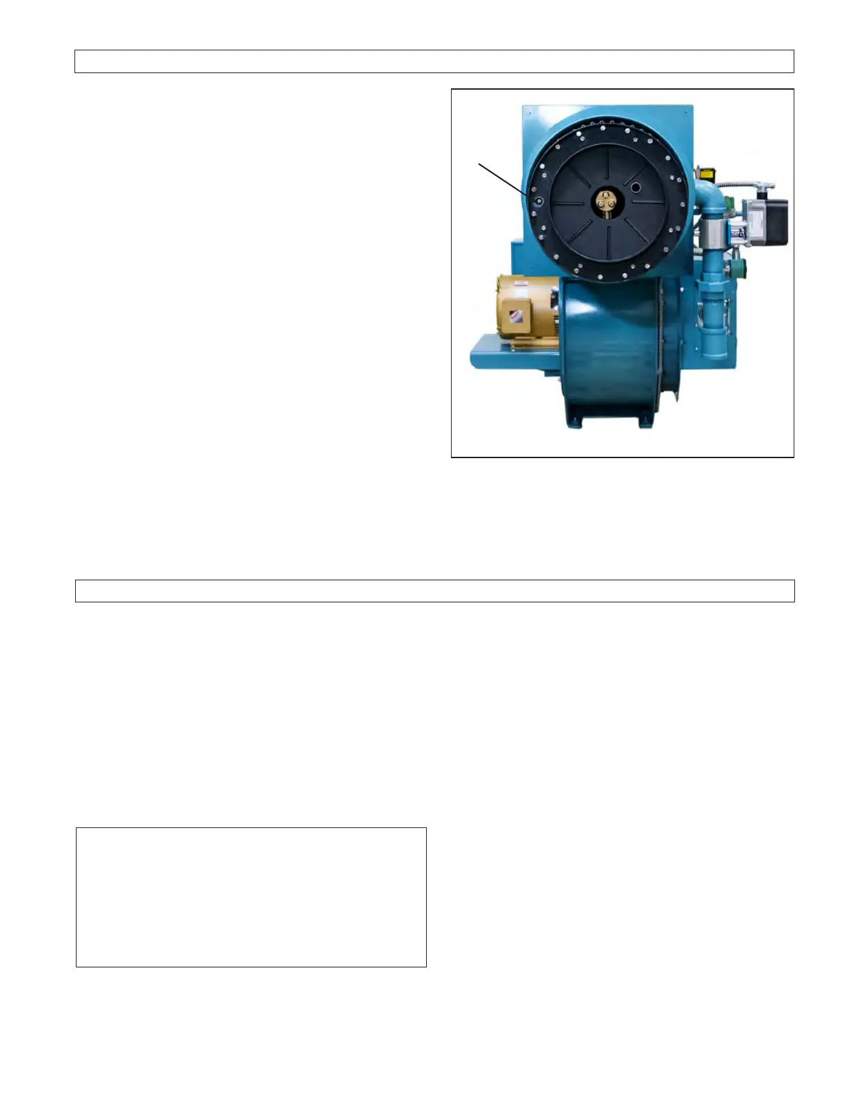
The spark plug position can be seen in gure H-1.
Pilot gas pressure should be measured at the 1/8” port
located downstream of the primary solenoid valve.
2. Air Damper Position
The air damper should be near close at low re and close
to full open at high re.
3. Gas Modulating Control Valve Position
The gas valve should be open about 10% at low re and
stroked at least 60% open at high re.
4. Oil Modulating Control Valve Position
For pressure atomizing, the low re position should be
adjusted to get the correct low re pressure, as stated on
the rating label. Typically, this would be 100 psi for simplex
systems and 65 psi for return ow nozzles. The high re
position should be about 45º to 60º travel from low re. For
air atomizing, the low re should be on about #2 position
and the high re should be about the #8 position.
Spark
Plug
I. STARTUP AND OPERATING ADJUSTMENTS
1. Pre-Start Check List
2. Burner Drawer Adjustments
3. Gas Setup
4. Pressure Atomized Oil Setup
5. Air Atomized, #2 Oil Setup
6. Operating Control Adjustments
7. Limit Tests
8. Pilot Test
9. Burner Shutdown
10. Restarting After Extended Shutdown
This section covers the startup and operating adjustments
of the Webster Models.
WARNING
BURNER STARTUP, COMBUSTION ADJUSTMENTS
AND LIMIT CONTROL ADJUSTMENTS SHOULD BE
PERFORMED ONLY BY TRAINED, EXPERIENCED
SERVICE TECHNICIANS. ATTEMPTING TO PER-
FORM THESE FUNCTIONS WITHOUT THE PROPER
TRAINING CAN RESULT IN EQUIPMENT DAMAGE,
PERSONAL INJURY OR DEATH.
operating and installation manual, as well as all control
manuals to verify that equipment is ready for operation.
These manuals must be read prior to start of equipment.
If you are not qualied to service this equipment, DO
NOT TAMPER WITH THE UNIT OR CONTROLS -
CALL YOUR SERVICEMAN.
A block diagram of the startup sequence for the SC
burner can be found on page 25, Figure I-3.
When nished with startup, document valve and linkage
positions, pressures, and settings for future reference.
READ AND SAVE THESE INSTRUCTIONS.
Figure H-1
During purge, all solenoids, including the gas separator
solenoid valve, are closed and are to remain closed until
called upon. After purging the system for at least
30 seconds, the spark plug is activated. Waiting for one
second for the spark to initiate, the pilot solenoid valve
is opened which will ignite the primary zone. When
the ame safeguard system detects a strong signal, it
will open the main fuel valve to start the ignition of the
secondary zone. Following a 4-second delay, the gas
separator solenoid valve will open and the pilot solenoid
can be closed. From this point on, the burner can be
driven to low re.
Before proceeding with startup and adjustment, be sure
that overall installation is complete. Review the boiler
Every burner set-up is different, therefore the positions
below are indications only and tuning must be done by
fully trained and qualied personnel.