Installation and Connection
3-6
3
3.1.5 Installation of the Inverter with Nema1 Kit (Optional, CFW11XXXXTXON1) on a Wall
Fixing holes position and diameter according to the figure 3.1.
External dimensions of the inverter with Nema1 kit according to the section 8.4.
Fasten the inverter.
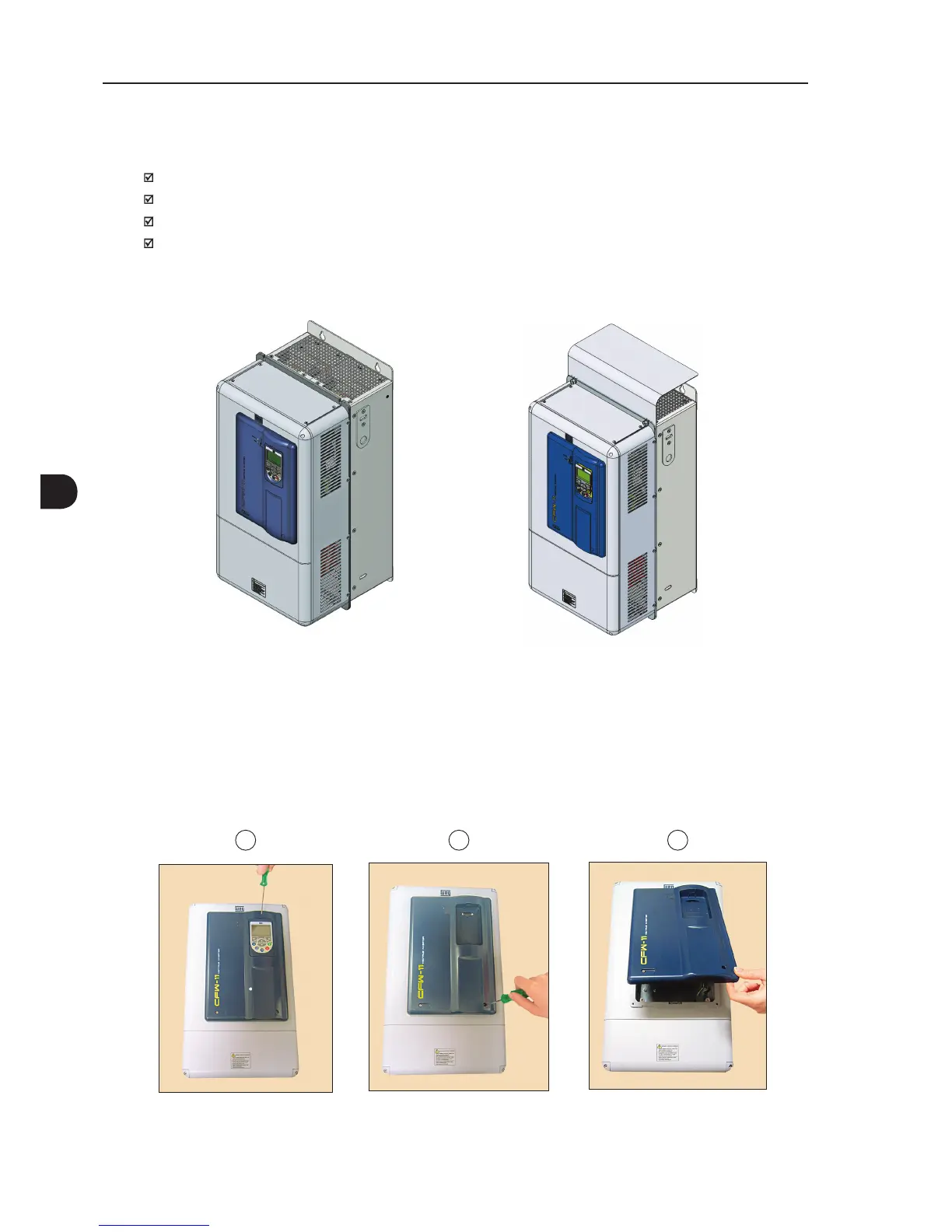
Install the Nema1 kit top on the inverter as showed in the figure 3.5 using the 2 M8 screws supplied with
the product.
Figure 3.5 - Installation of the Nema1 kit top (“hat”)
3.1.6 Access to the Control and Power Terminal Strips
In order to get access to the control terminal strips, the HMI and the cover of the control rack must be removed,
as showed in the figure 3.6.
Figure 3.6 - HMI and control rack cover removal
321
 Loading...