WECM / Emerald eZA Manual | 13
www.weg.net
Notes:
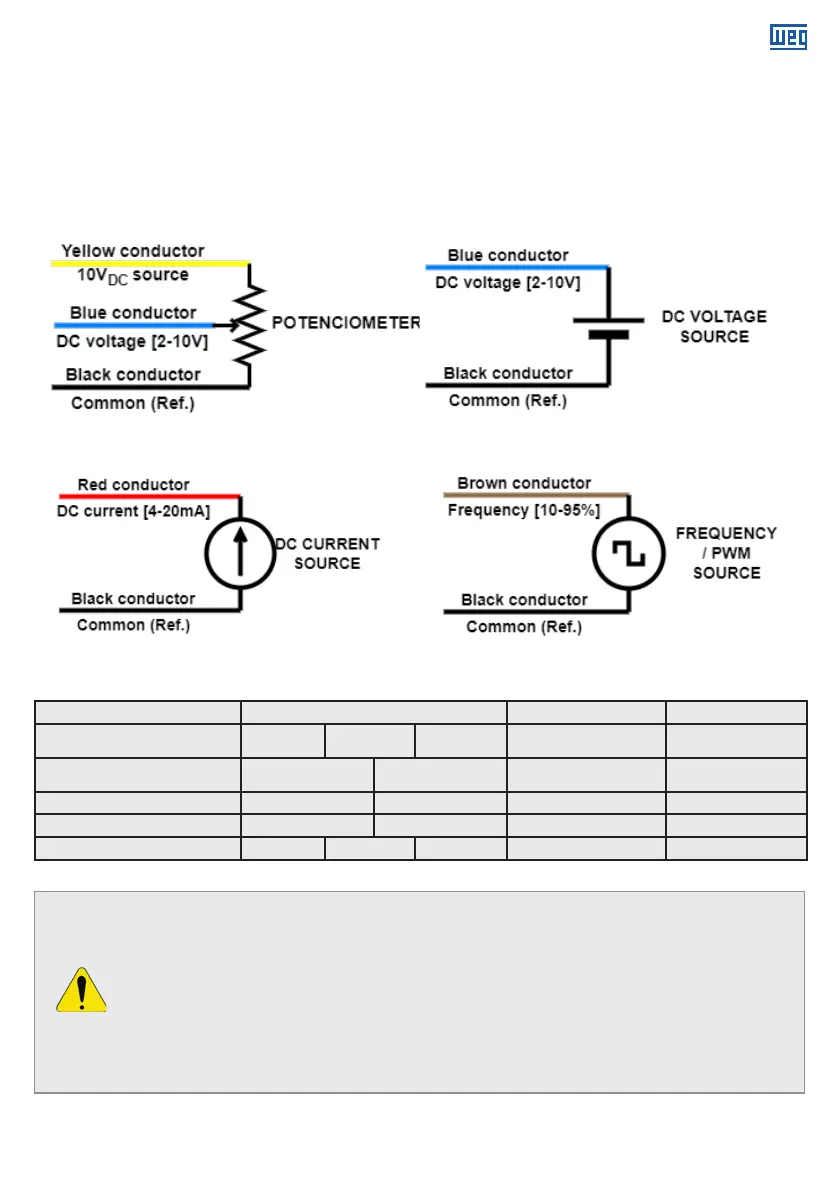
a. The DC voltage signal can be applied by an external power supply or using the built-in
10VDC source and an additional potentiometer (5kΩ to 10kΩ);
b. Maximum speed adjusted (see item 6.3);
c. Solution minimum speed (lowest value of the speed range);
d. Input signal (V DC, mA DC, %) supplied to the respective remote input.
Figure 7 - DC voltage input
(using built-in power supply)
Figure 8 - DC voltage input
(using external power supply)
Figure 9 - DC current input
Figure 10 - Frequency input
Control cable electrical connections diagram:
ATTENTION!
g
The built-in power supply has an output limit of 25mW or 2,5mA;
g
The product can be permanently damaged if imposed signals out of the specifi-
cation;
g
Make sure that all unused conductors in control cable are insulated to avoid prod-
uct malfunction or damage.
g
The connection between the Yellow cable (10VDC power source) and the red
cable (DC current) will damage permanently the DC current speed control.
Recommendation for maximum conductors’ length to avoid signal drop for each connection type.
Signal Type Conductors Maximum Length (m) Cable specification
DC voltage
(built-in power supply)
Yellow Blue Black 150 m 24 AWG
DC voltage
(external power supply)
Blue Blue 150 m 24 AWG
DC current Red Blue 150 m 24 AWG
Frequency Brown Blue 150 m 24 AWG
Modbus (optional) Yellow Red Black 150 m 24 AWG
Table 7 - Maximum conductors' length recomended for signal wires
 Loading...