Weichai America Corp.
Revision: October 2018 20
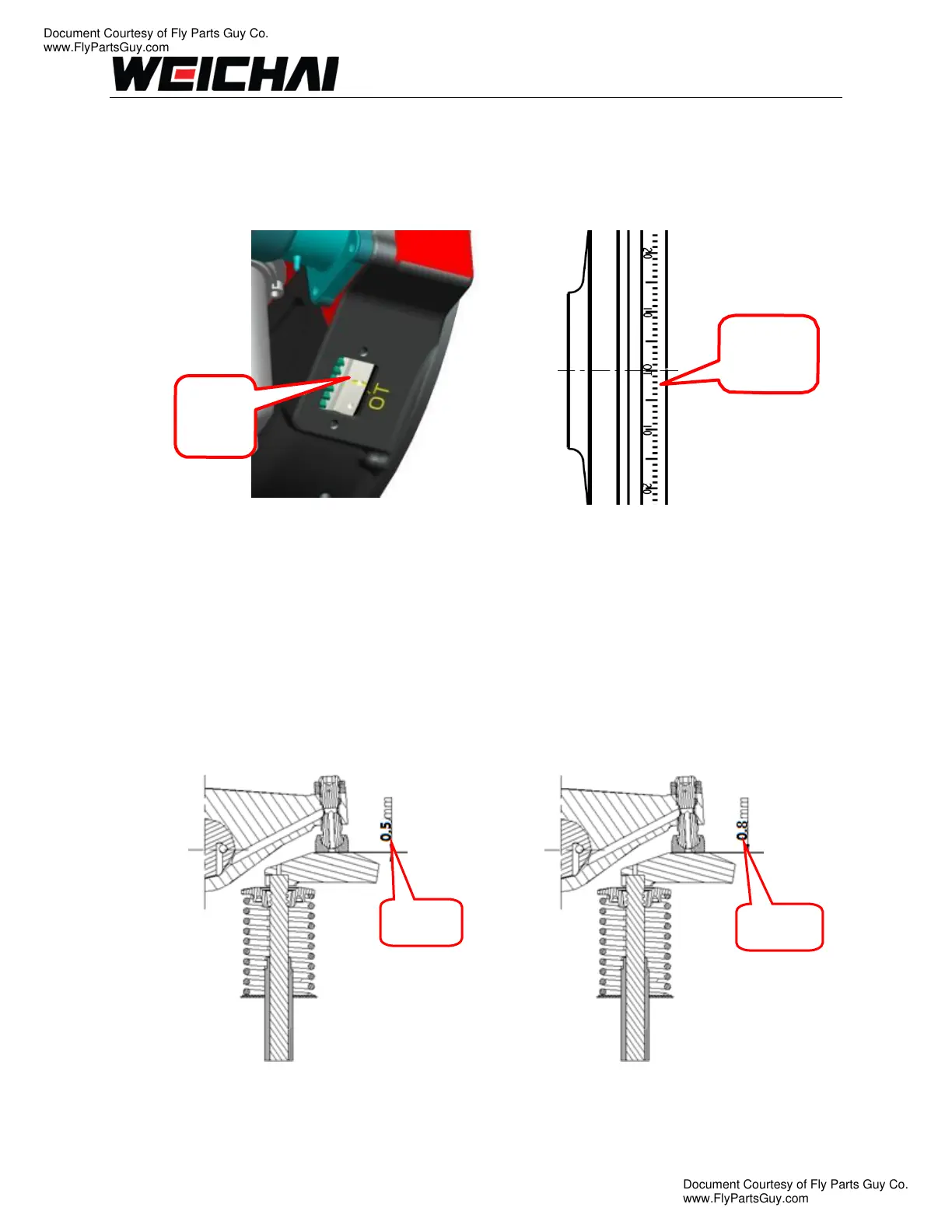
B. Rotate the crankshaft until the number 1 piston is on the compression stroke and the
timing pointer on the front cover is in-line with the “TDC” mark on the crankshaft
damper. Some engines may have a permanent groove mark on the flywheel for
“TDC”.
Illustration 5 Illustration 6
C. Using Illustration 9, adjust the six (6) valves corresponding with cylinder 1 “TDC”. Insert
the correct feeler gauge between the rocker arm and valve stem tip. Loosen the locknut
and turn the valve adjustment screw until the rocker arm and valve stem tip contact the
feeler gauge.
D. Tighten the locknut once the valve is adjusted properly. Remove the feeler gauge. A
very slight resistance should be felt when removing the feeler gauge.
Illustration 7 Illustration 8
Located
on
Located on
Vibration
Damper
intake
exhaust
Document Courtesy of Fly Parts Guy Co.
www.FlyPartsGuy.com
Document Courtesy of Fly Parts Guy Co.
www.FlyPartsGuy.com