13
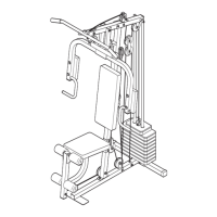
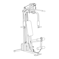
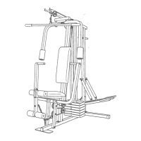
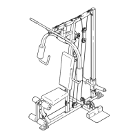
32. Route the Low Cable (47) through the Seat
Upright (73) and under a 90mm Pulley (38).
Attach the Pulley and a pair of Pulley Covers (44)
inside the Seat Upright with an M10 x 68mm Bolt
(59), two M10 Washers (26), two 8mm Spacer
(51), and an M10 Nylon Locknut (71). Make sure
the small tabs on the Pulley Covers are on the
bottom.
See the inset drawing. Attach the end of the
Low Cable (47) to the Leg Lever (4) with an M8 x
27mm Shoulder Bolt (63) and an M8 Nylon
Locknut (70).
73
51
51
38
26
26
59
47
44
44
71
32
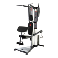
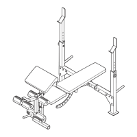
33. Orient the Seat (16) as shown. Attach the Seat to
the Seat Frame (5) with an M6 x 65mm Screw
(65), an M6 Washer (35), and two M6 x 15mm
Screws (66).
16
35
65
5
66
W
ide
End
33
SEAT ASSEMBLY
4
47
63
70
Small
Tab
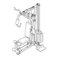
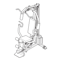
30. Wrap the Low Cable (47) over a 90mm Pulley
(38). Attach the Pulley and a pair of Pulley
C
overs (44) to the Large “U”-bracket (82) with an
M10 x 53mm Bolt (61) and an M10 Nylon Locknut
(
71). M
ake sure the small tabs on the Pulley
Covers are on the bottom.
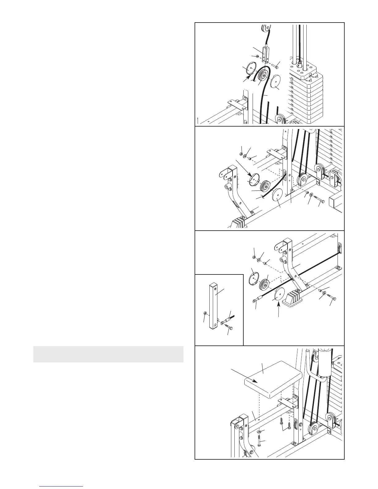
31. Wrap the Low Cable (47) under a 90mm Pulley
(38). Attach the Pulley and a pair of Pulley
Covers (44) inside the Front Upright (6) with an
M10 x 68mm Bolt (59), two M10 Washers (26),
two 8mm Spacer (51), and an M10 Nylon Locknut
(71).
Make sure the large tabs on the Pulley
Covers are oriented as shown.
6
1
8
2
38
47
44
44
71
3
0
6
51
51
38
26
26
59
47
44
44
71
31
Small Tab
Large Tab