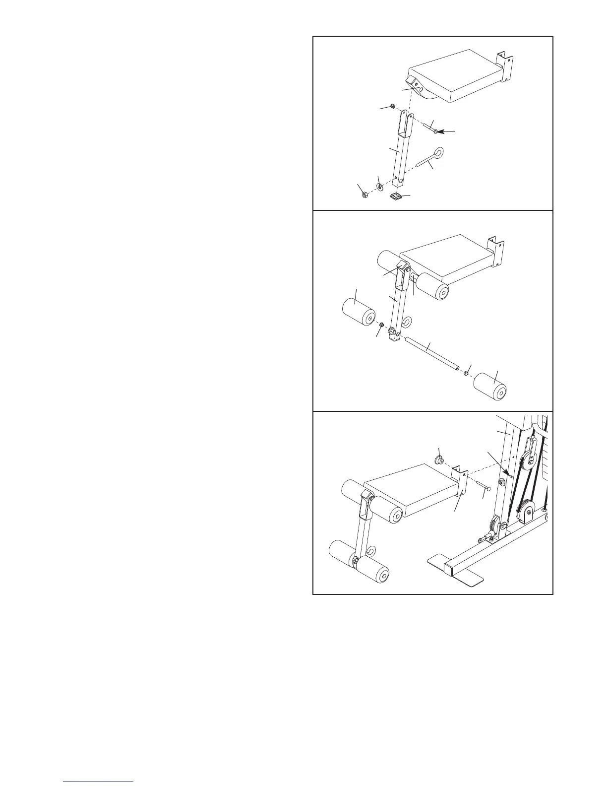
35. Press a 38mm Square Inner Cap (29) into the
Leg Lever (8).
Attach the M10 x 63mm Eyebolt (97) to the Leg
L
ever (8) with an M10 Large Washer (108) and
an M10 Nylon Locknut (72).
Lubricate an M8 x 57mm Bolt (79) with grease.
Attach the Leg Lever (8) to the Seat Frame (7)
with the Bolt and an M8 Nylon Locknut (73). Do
not overtighten the Locknut; the Leg Lever
must be able to pivot easily.
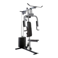
36. Press two 19mm Round Inner Caps (27) into a
Pad Tube (26). Slide the Pad Tube into the hole
in the Leg Lever (8). Slide two Small Foam Pads
(66) onto the Pad Tube.
Assemble the other Pad Tube (26) to the Seat
Frame (7) in the same manner.
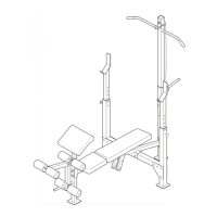
37. Set the Seat Frame (7) on the pin on the Front
Upright (4). Secure the Seat Frame with an M8 x
67mm Carriage Bolt (82) and the M8 Knob (106).
35
36
37
79
L
ubricate
72
108
29
73
7
97
8
26
27
27
66
66
8
7
26
7
106
Pin
82
4
38. Make sure that all parts are properly tightened. The use of all remaining parts will be explained in ADJUST-
MENT, beginning on the following page. Before using the weight system, pull each cable a few times to
make sure that the cables move smoothly over the pulleys. If one of the cables does not move smoothly,
locate and correct the problem before using the weight system.
IMPORTANT: If the cables are not proper-
ly routed, they may be damaged when heavy weight is used. See the CABLE DIAGRAM on page 20
of this manual.
15