8
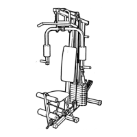
2. Insert six M8 x 75mm Carriage Bolts (83) up
through the Left Base (119). Note: It may be
helpful to place a piece of tape over each
Bolt head to hold it in place.
2
3
119
83
83
83
1
78
78
119
103
103
100
1
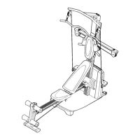
3. Attach the Right Base (1) to the Left Base (119)
with two M8 x 80mm Bolts (100), two M8
Washers (103), and two M8 Nylon Locknuts
(78).
Do not tighten the Nylon Locknuts yet.
1.
Insert four M8 x 75mm Carriage Bolts (83) up
through the Right Base (1).
Note: It may be
helpful to place a piece of tape over each
Bolt head to hold it in place.
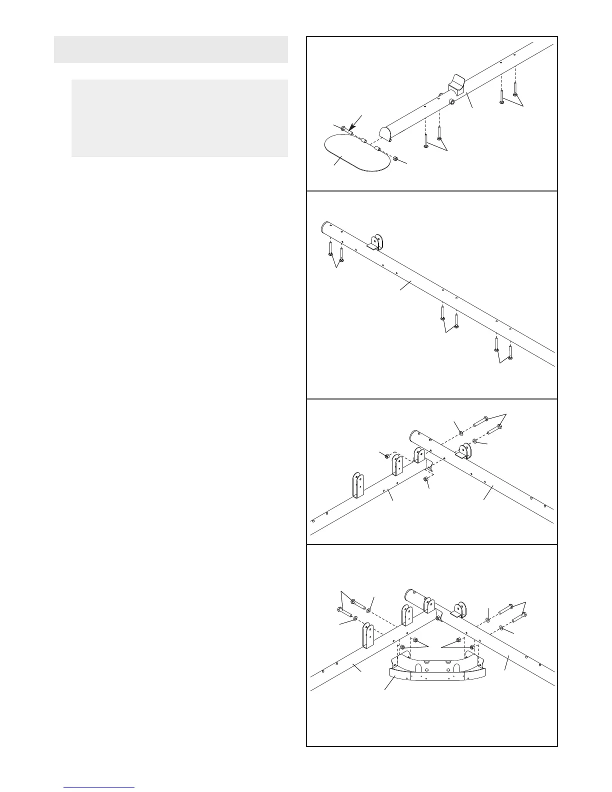
Apply a portion of the included grease to an
M10 x 141mm Bolt (141). Attach the Foot Plate
(146) to the Right Base (1) with the Bolt and an
M10 Nylon Locknut (77).
Do not overtighten
the Nylon Locknut; the Foot Plate must
pivot freely.
B
efore beginning assembly, make sure
you understand the information in the
box on page 7. See the PART IDENTIFI-
CATION CHARTS on pages 5 and 6 for
h
elp identifying small parts.
Frame Assembly
83
77
141
Grease
146
8
3
1
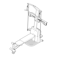
4. Attach the Bottom Center Base (147) to the
Right and Left Bases (1, 119) with four M8 x
80mm Bolts (100), four M8 W
ashers (103), and
four M8 Nylon Locknuts (78).
Do not tighten
the Nylon Locknuts yet.
4
100
100
103
103
103
103
78
1
147
119