9
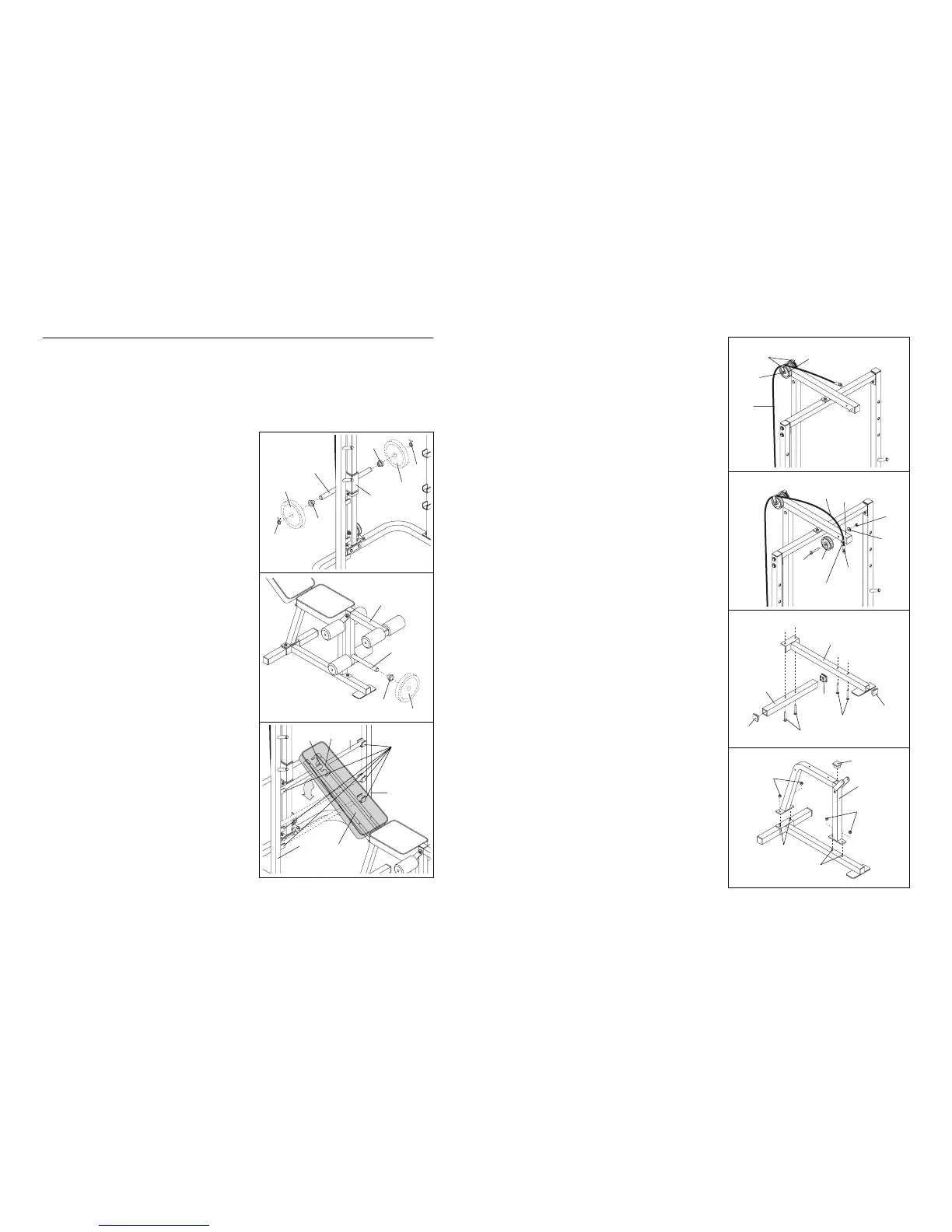
9. Route the Cable (51) around the indicated Pulley
(24). Tighten the M10 Nylon Locknut (2) and the
M10 x 120mm Bolt (not shown). Do not overtighten
the Nylon Locknut. Be sure that both Cable
Traps (23) are turned as shown and that the
Cable and Pulleys move smoothly.
10. Wrap the Cable (51) around a Pulley (24). Attach
the Pulley to the Top Frame (21) with an M10 x
89mm Bolt (9), an M10 Washer (10), and an M10
Nylon Locknut (2). Be sure that the cable stop is
on the indicated side of the Pulley and that the
Cable is between the Pulley and the welded
post.
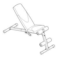
11. Press a 2Ó Square Inner Cap (46) into each end of
the Stabiliser (33). Press a 2Ó Square Inner Cap
(46) into the end of the Bench Base (43).
Insert two M8 x 60mm Carriage Bolts (3) up
through the Stabiliser (33). Slide the end of the
Bench Base (43) onto the Carriage Bolts.
Insert two M8 x 60mm Carriage Bolts (3) up
through the Bench Base (43).
12. Slide the Bench Frame (49) onto the M8 x 60mm
Carriage Bolts (3). Tighten an M8 Nylon Locknut (4)
onto each Carriage Bolt.
Press a 2Ó Square Inner Cap (46) into the Bench
Frame (49).
12
9
2
24
23
2
10
21
24
51
9
51
10
11
46
46
43
46
33
3
4
4
3
3
49
46
3
12
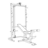
ADJUSTING THE WEIGHT BENCH
The weight bench is designed to be used with your own weight set (not included). The steps below explain how
the weight bench can be adjusted. See EXERCISE GUIDELINES on page 14 for important exercise information.
Refer also to the exercise information accompanying your weight set (not included) for additional exercises.
Inspect and tighten all parts each time you use the weight bench. Replace any worn parts immediately. The
weight bench can be cleaned with a damp cloth and a mild, non-abrasive detergent. Do not use solvents.
ATTACHING WEIGHTS TO THE WEIGHT CARRIAGE
To use the high or low pulley station, first slide a Weight
Stop (35) onto each side of the weight tube of the Weight
Carriage (52). Slide the desired amount of weight (not
included) onto the weight tube. Be sure that an equal
amount of weight is on each side of the weight tube.
Secure the weights on each side of the weight tube with a
Spring Clip (44).
ATTACHING WEIGHTS TO THE LEG LEVER
To use the Leg Lever (32), be sure there is a Weight Stop
(35) on the weight tube. Then slide the desired amount of
weight (not included) onto the weight tube.
ADJUSTING THE BACKREST
The Backrest (29) can be set at three different positions:
the level position, the decline position, and the incline posi-
tion.
To change the position of the Backrest (29), move the
Adjustment Tube (31) to a different set of adjustment
brackets on the Left and Right Uprights (18, 19). Make
sure that the Adjustment Tube is securely seated in
the adjustment brackets and that it is also firmly seat-
ed in one of the slots in the Adjustment Backrest
Bracket (26).
Weight
Weight
Weight
Tube
Cable
Stop
Welded
Post
44
44
35
52
32
31
26
18
19
Slots
Adjustment
Brackets
35
Weight
Tube
29
Weight
35
 Loading...