CWH companion water heater — Product Manual
Figure 7 Time lag to obtain hot water at fixture for
branch lengths of 10 and 25 feet (ASPE
Domestic Water Heating Design Manual)
Time in seconds required to get hot water at fixture
Fixture flow rate (GPM) 0.5 1.5 2.5 4.0
Piping length (feet) - 10 25 10 25 10 25 10 25
Copper pipe ½” 25 63 8 21 5 13 3 8
¾” 48 119 16 40 10 24 6 15
Steel pipe ½” 63 157 21 52 13 31 8 20
¾” 91 228 30 76 18 46 11 28
CPVC pipe ½” 64 159 21 53 13 62 8 20
¾” 95 238 32 79 19 48 12 30
NOTE: Select branch size and length for less than 31 seconds
delay.
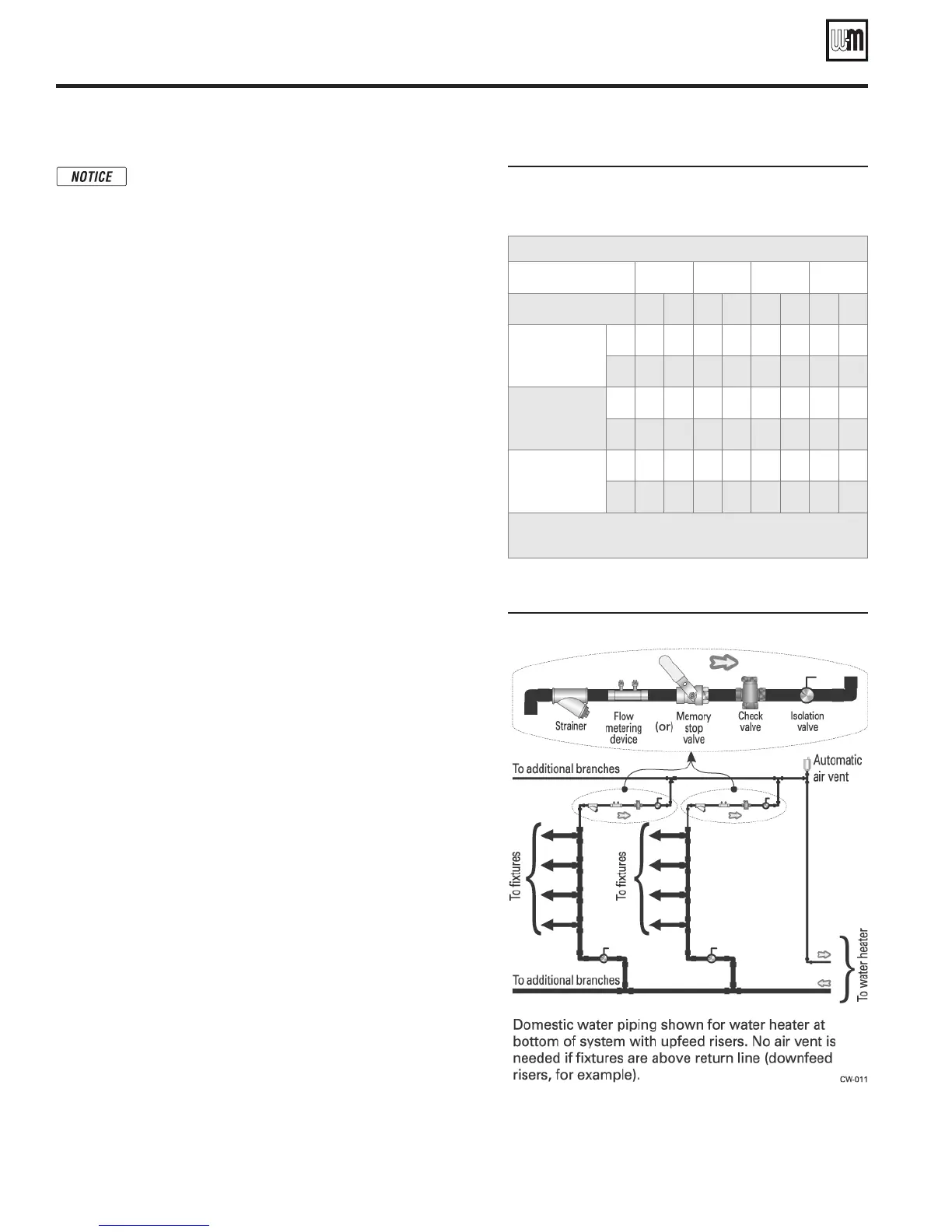
Figure 8 Recirculation components
Massachusetts code applications require recirculation
piping or heat-traced piping if the distance from the
water heater to the furthest fixture exceeds 100 feet.
Maintaining domestic water temperature
in the supply piping
1. Recirculation is used to reduce wait time for water use, to minimize
hot water and energy waste caused during the waiting period, and
to prevent degradation of the system supply water temperature.
ASPE recommends recirculation when the distance from the water
heater to the furthest fixture exceeds 100 feet or the time lag for
hot water to reach a fixture(s) exceeds 30 seconds.
2. Consult local codes and American Society of Plumbing Engineers
(ASPE) Domestic Water Heating Design Manual, 1998, for further
information.
Time delay at fixtures
1. Figure 7 is from the ASPE Domestic Water Heating Design Manual,
1998. It shows the time required for usable hot water to arrive at a
fixture based on the fixture flow rate (available from industry and
manufacturer’s data) and the length and diameter of the dead-end
branch pipe supplying the fixture.
2. The time lag should generally not exceed 30 seconds.
3. For residential and office applications, the owner may prefer a
limit of 10 seconds.
4. You can use Figure 7 as a guide to determining the location of
circulation return lines relative to fixtures.
Balancing
1. When multiple branches are connected to the supply piping, each
branch must be connected to the recirculation system.
a. At each of these connections to the return piping, install shutoff
valves, a flow metering device, check valve and a strainer as
shown in Figure 8.
b. Check local codes for specific installation requirements.
2. These branches must be balanced to prevent pipe erosion and
unacceptable time delays at some fixtures.
3. Balancing options include circuit setters, memory stop valves or
factory preset devices (with flow metering provision in the piping).
Components required
1. For residential applications, consult circulator manufacturer’s
data for circulator selection and additional components required.
2. On most commercial systems, install the devices shown in Figure 8,
and any other devices or piping methods required by local codes.
a. The check valves are required to prevent fixtures from taking
hot water through the return lines.
b. Shutoff valves are needed to allow cleaning and replacing
balancing devices.
c. Include strainers to remove sediment which could damage the
circulator and / or affect the flow balancing devices.
Recirculation (if used)
Part number 635-500-156/0113
10