���
I 2000/K 2000
Assembly instructions | Notice de montage Version | Version 05.08.2019
Reserve technical changes | Sous réserve de modifications techniques Item no. | N° art. 115729-0000 Page | Page 10/32
Notice de montageAssembly instructions
Back wall section without punched holes
Mark the future location of the awning brackets on the back wall.
In doing so, please take into account the position of the pre-assem-
bled
arms, rafters, etc. as well as the sliding supports if applicable.
Drill holes of about 40 mm in diameter into the back wall section
using an aerial drill, for example.
• Take the grooves in the wall brackets into account.
• Trace the centre drill holes, remove the back wall section.
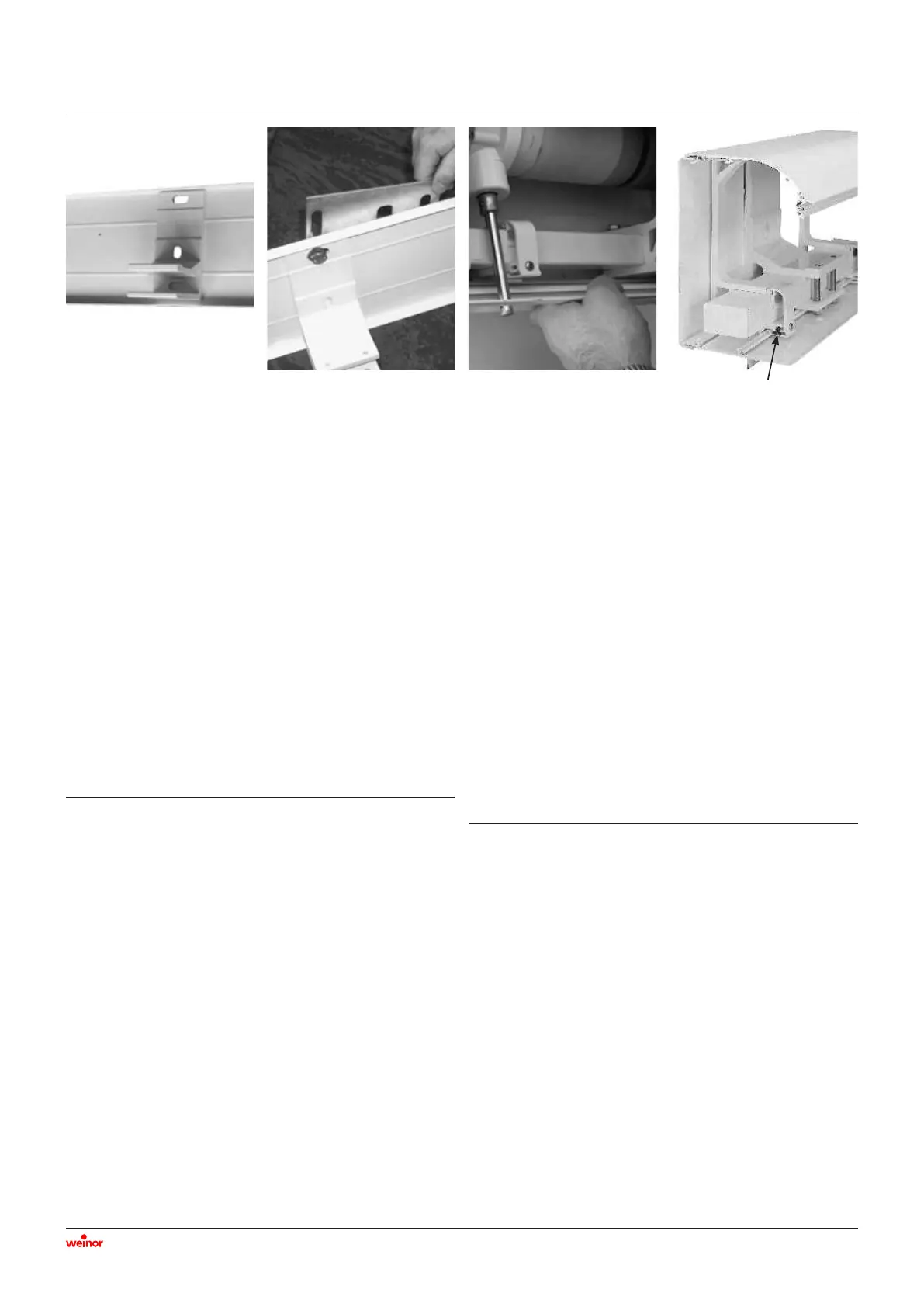
• Drill the marked holes, hold up the back wall, and mount, align
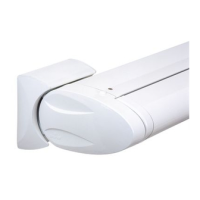
and secure the awning brackets (Pict 3.6).
• Now drill the upper drill holes and secure all the awning brackets.
• Check the alignment of the back wall section using a plumb line
and pad out with base plates if necessary.
• To do so, loosen the screws as needed.
• “Hang” the base plates (Pict 3.7).
• Tighten the awning bracket screws.
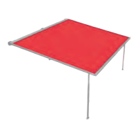
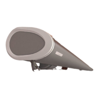
• Slide the awning or carrier bar into the awning brackets.
• Insert the securing bolts from underneath and tighten (Pict 3.4).
• Clip on the cover caps (Pict 3.5).
���
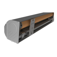
3.1.2 Affixing the bottom section
• Open the awning about 50 cm.
• Insert the bottom section into the back section of the roof bracket.
Then push in the front section of the roof bracket (Pict 3.8).
• Do not loosen the screw holding in the bottom section clip.
• Insert the clip for the hood bracket (Pict 3.9) into the bottom
section clip.
• Affix the casing end caps to the bottom section using 2 screws.
Profilé du mur arrière sans perforation
Le futur emplacement des consoles est reporté sur le mur arrière.
Tenir compte de la position des bras prémontés, des supports de
toit etc. et le cas échéant du palier lisse. Percer des trous de 40 mm
de diamètre environ dans le profilé du mur arrière avec un foret
conique étagé par exemple.
• Tenir compte des rainures dans les consoles murales.
• Marquer l’emplacement des trous centraux et retirer le profilé
du mur arrière.
• Percer les trous aux emplacements indiqués, retenir le mur
arrière puis placer, aligner et visser les consoles (Pict 3.6).
• À présent percer uniquement les trous supérieurs et visser toutes
les consoles.
• Avec la ficelle de maçon, vérifier que le profilé du mur arrière
ne doit pas être étayé avec des cales d’épaisseur par exemple.
• Pour ce faire, desserrer les vis.
• « Accrocher » les cales d’épaisseur (Pict 3.7).
• Serrer les vis des consoles.
• Glisser le store resp. le tube de support dans les consoles.
• Insérer les vis de blocage par le bas et les serrer (Pict 3.4).
• Clipser les caches (Pict 3.5).
���
3.1.2 Fixation du profilé du fond
• Sortir le store d’env. 50 cm.
• Glisser le profilé du fond dans la partie arrière du support de
toit. Enfoncer ensuite la partie avant du support de toit
(Pict 3.8).
• Ne pas desserrer la vis du clip du profilé du fond.
• Insérer la fermeture à clip (Pict 3.9) dans le clip du profilé du
fond.
• Fixer les embouts du caisson au profilé du fond avec 2 vis.
Pict 3.6 Pict 3.7 Pict 3.8 Pict 3.9: Clip lock
Fermeture à clip
 Loading...