���
I 2000/K 2000
Assembly instructions | Notice de montage Version | Version 05.08.2019
Reserve technical changes | Sous réserve de modifications techniques Item no. | N° art. 115729-0000 Page | Page 13/32
Notice de montageAssembly instructions
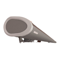
3.4 Fixation dans une niche
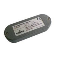
• Les consoles murales spéciales « niche » (Pict 3.15) permettent
d’insérer des vis de blocage pour console par le dessus. Pour cela,
des vis à tête conique sont utilisées pour toutes les consoles.
• Suivre la procédure de montage pour les stores avec profilé du
fond et profilé du mur arrière (cf. section 3.1.1)
à une exception près :
Fixer le profilé du fond et les embouts du caisson avant
d’accrocher le store (dans les consoles murales). Visser
les vis de blocage pour console par le dessus et sortir le
store de 50 cm environ.
���
4. Réglage de l’inclinaison : types I 2000 et K 2000
• Plage de réglage de l’inclinaison : de 5° à 40°.
Même si la plage de réglage le permet, ne jamais régler
le store de sorte qu’il s’ouvre vers le haut.
• Sortir le store pour effectuer le réglage de l’inclinaison.
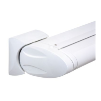
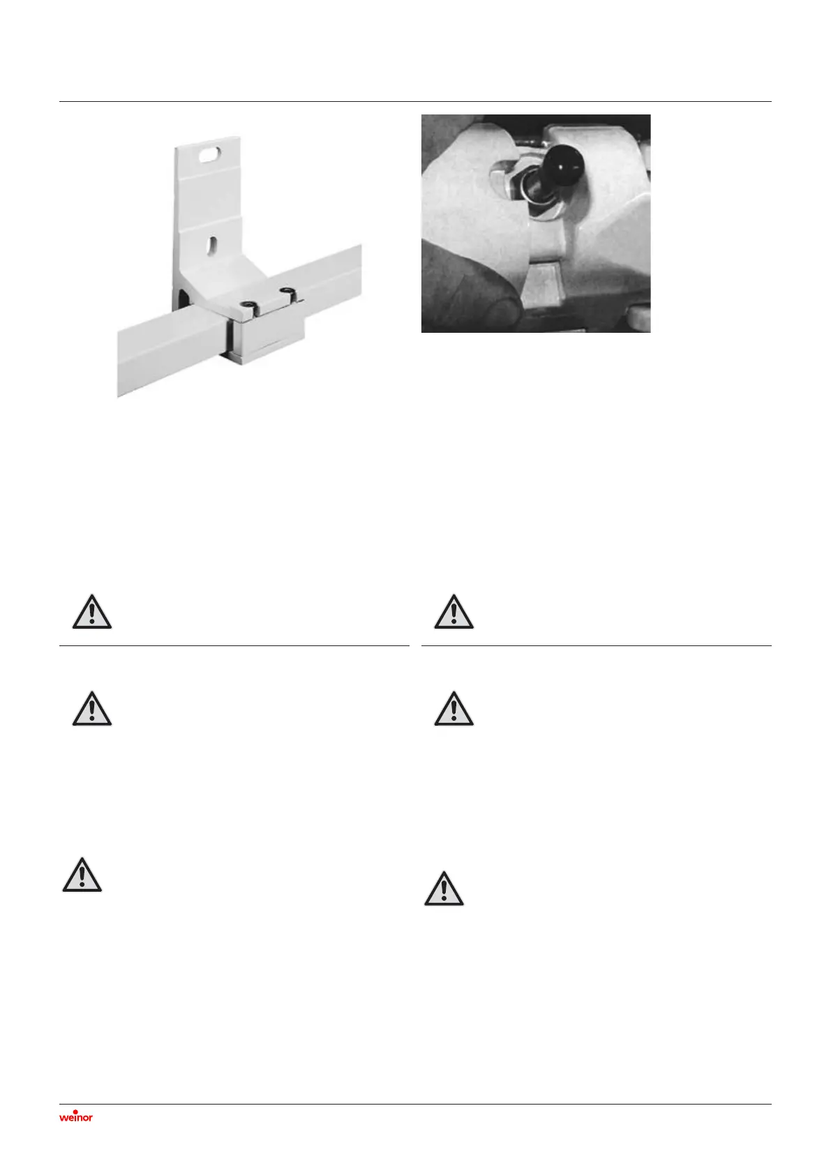
• Glisser le coulisseau de la pièce d’inclinaison (Pict 4) sur le côté
avec la main. L’écrou de serrage est alors visible.
• Décharger l’écrou lors du réglage de l’inclinaison en soulevant
les bras !
• Ajuster l’écrou à l’aide d’une clé à pipe de 17 (paroi fine).
• Rotation vers la droite : le bras est relevé.
• Rotation vers la gauche : le bras est abaissé.
L’écrou de serrage peut être dévissé jusqu’à 1 mm maxi-
mum de l’extrémité de la vis à œillet.
• Régler l’inclinaison de tous les bras de la même manière.
• Retirer le cache des vis à œillet lorsque l’inclinaison est réglée à
plus de 15°.
Pict 4
Pict 3.15
3.4 Niche assembly
•
The special “niche” wall fixings (
Pict
3.15) enable the bracket
securing bolts to be inserted from above. For this purpose,
countersunk bolts are used for all brackets.
•
Follow the fitting procedure for awnings with bottom section
and back wall profile (see para. 3.1.1)
but with the following exceptions:
Fit the bottom section and box end caps before hang-
ing the awning (onto the wall brackets). Screw in the
bracket securing bolts from above by extending the
awning by approx. 50 cm.
���
4. Angle adjustment: models I 2000 and K 2000
• Range of pitch: 5 degrees to 40 degrees.
Even if the adjustment range permits it, never set the
awning angle so that it is going upwards.
• To adjust the awning pitch, first extend the awning.
• Push the slides of the tilting section by hand to the side (Pict 4)
to expose the locking nut.
• Whilst setting the pitch of the awning, lift the arm to screw.
• Adjust the nut with a no 17 box spanner (thin wall).
• Turn to the right to set the arm.
• Turn to the left to set the arm lower.
The locking nut may only be unscrewed to max 1 mm
beyond the end of the eyebolt.
• All arms should be adjusted to the same angle.
• Remove the cap of the eyebolts when setting the pitch to over
15 degrees.
 Loading...