25
STEP 5
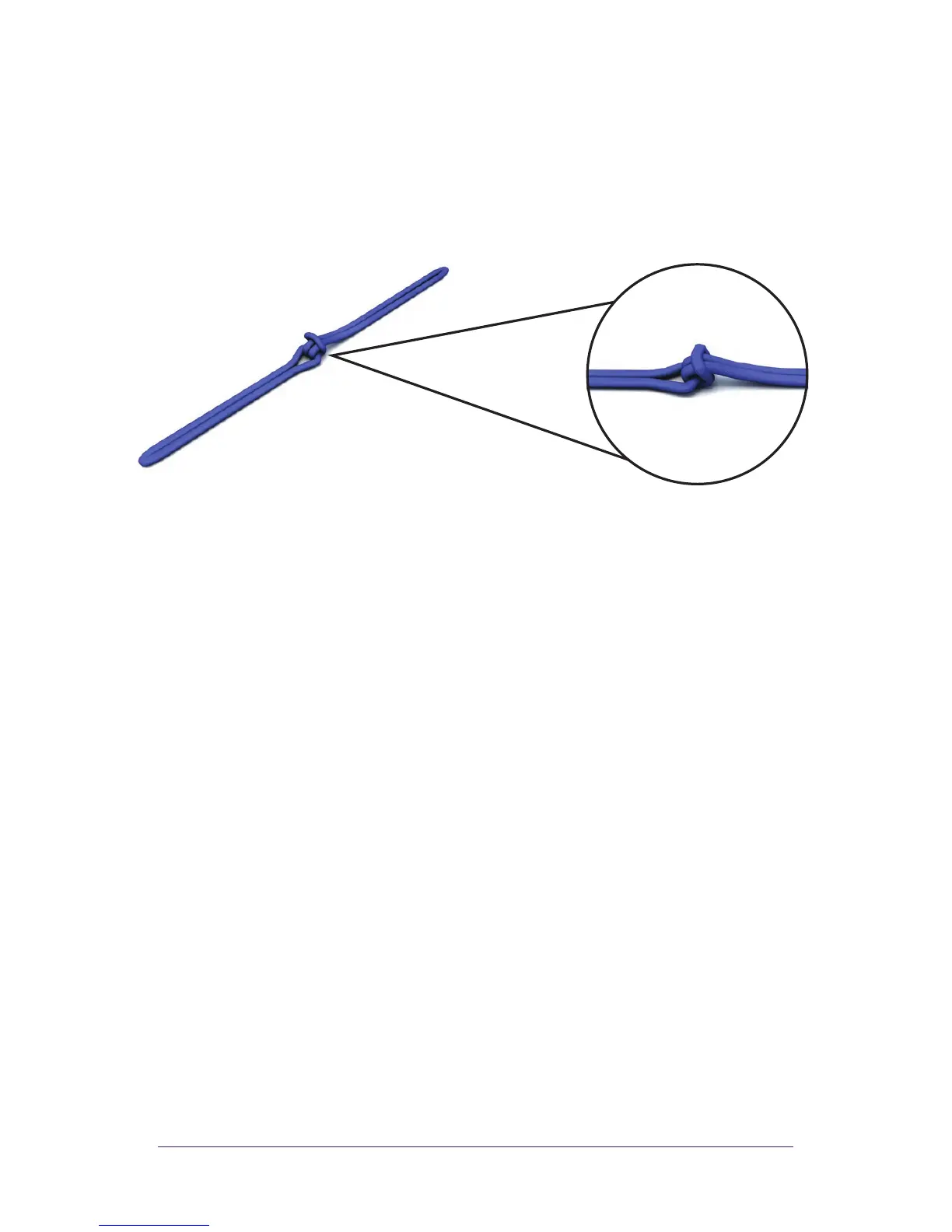
With “C” end pulled taut, notice how “D” and “C” ends have
switched places. Keeping “A/B” SPM
®
FSR stationary, keep pulling
“C” end until the “B/D” connection can no longer be tightened.
SPM
®
FSR link should look like detail shown.
NOTES:
a) LINKING is described in the above procedure. NEVER tie knots
in SPM
®
FSR components. Use only the linking method to attach
restraint ends to each other.
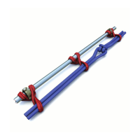
b) Every Spine-to-Spine link must be tight. This is critical in
establishing an overall tight SPM
®
FSR.
c) This linking procedure generally applies only to SPM
®
FSR
Spines. However, SPM
®
FSR Ribs can be linked in the same
manner if a single Rib is too short to encircle a larger component.
d) SPM
®
FSR Spines are rated at over twice the strength of SPM
®
FSR Ribs. Spines and Ribs should NEVER be linked together.
e) As an extension of (d) above, SPM
®
FSR Ribs may NEVER be
substituted for SPM
®
FSR Spines.
f) Linked Spines should run parallel down the main line and not
twist or be wrapped around the flow line.
g) Spines can also be linked together using approved FSR shackles.
END “D”
END “B”
END “C”
END “A”