Do you have a question about the WELBA MRF-2 Series and is the answer not in the manual?
Details on the intended use and importance of the operating instructions for safe installation and operation.
Manufacturer's disclaimer of liability for damages due to improper installation or use of the device.
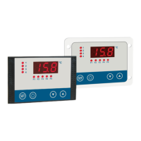
Overview of MRF-2 | MRH-2 controllers, their functions, inputs, outputs, and software.
Information on controller designation, connection diagrams, and technical details found on the type plate.
List of components included with the MRF-2 | MRH-2 controller package.
Guidelines for proper disposal of electronic equipment according to WEEE directive.
Instructions for cleaning the controller enclosure front, with warnings about unsuitable cleaning agents.
Detailed dimensions and panel cut-out sizes for MRF-2 and MRH-2 controller housings.
Detailed technical specifications including operating voltage, inputs, outputs, environmental and electrical safety data.
General safety advice, including operator instructions, parameter settings, and responsibility for commissioning.
Specifies the intended industrial applications for the controller and restrictions on other uses.
Guidelines for safe wiring, earthing, and precautions to prevent electrical hazards.
Recommended installation environment, climatic conditions, unpacking, and storage procedures.
Step-by-step instructions for mounting the MRF-2 and MRH-2 controller housings into panel cutouts.
Guidance on connecting the temperature sensor, avoiding damage, and the importance of correct parameter settings.
Crucial safety precautions before making electrical connections, including mains voltage checks and disconnecting power.
Step-by-step procedure for safe and correct electrical connection of the controller and its components.
Guidelines for correct wiring, material selection, and reference to circuit diagrams for connections.
Important advice for starting operation, parameter adjustment, system design, and using the WELBA KONSOFT software.
Diagram and explanation of the controller's components and modular architecture.
Explanation of the controller's LEDs, display, and the functions of its buttons in the working level.
Detailed explanation of how controller blocks and function blocks function and can be configured.
A step-by-step guide to quickly setting up the controller's parameters for various functions.
Description of the different operating levels for parameter access and how to navigate them.
Overview of parameter lists structured by level and type, including C, P, H, and D parameters.
Detailed list of C-parameters for setpoints, alarms, and hysteresis, with their ranges and default values.
List of P-parameters for controller block configuration, relay functions, and output assignments.
List of H-parameters for configuring temperature alarms, their assignment, and special functions.
List of d-parameters for hardware configuration, sensor selection, analogue input, and button functions.
Procedure for correcting sensor readings using a reference thermometer and adjusting parameters C90/C92/C94.
Table detailing fault codes indicated by LED display or text and their corresponding causes and remedies.
Guidance on minimizing interference and ensuring reliable operation of electronic control systems in industrial environments.
Methods for reducing electrical interference in DC and AC systems using diodes, RC combinations, and other components.
| Category | Controller |
|---|---|
| Input Voltage | 24 VDC |
| Output Current | 2A |
| Operating Temperature | -10°C to +50°C |
| Protection Class | IP20 |
| Frequency Range | 50Hz - 60Hz |