27
IOM-224 MODEL: INLOOP™ ACE REV: A 13839 West Bellfort Street, Sugar Land, TX 77498 welker.com Service Department 281.491.2331
Check Valves
69. Screw down the adjustment screw to expose the wrench flats on the shaft.
70. Apply medium strength thread-locking fluid to the shaft adapter threads, and then screw the shaft adapter into the
shaft (Figure 14). While holding the shaft with a wrench, use a second wrench to screw the shaft adapter into the shaft.
71.
Insert the internal inlet check valve into the piston (Figure 14). Ensure that the correct poppet and spring are installed.
72. Apply medium strength thread-locking fluid to the piston threads, and then screw the piston into the shaft adapter
(Figure 14). While holding the shaft with a wrench, use a second wrench to screw the piston into the shaft adapter.
73.
Insert the internal outlet check valve into the cylinder base (Figure 15). Ensure that the correct poppet and spring are
installed.
74.
Screw the cylinder base onto the cylinder top (Figure 15).
Completing Reassembly
75.
Screw the cylinder top into the bottom of the body (Figure 13).
76.
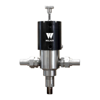
Carefully install the body with cylinder base and top to the motor housing (Figure 15). Use two (2) wrenches to tighten.
77. Tighten all mating bodies to ensure there are no gaps.
78.
If the inLoop™ ACE is equipped with optional equipment, install the assembly to the cylinder base (Figure 11).
79. If applicable, replace the O-ring in each VCOconnection.
80. The unit is now ready for installation.