12
ADJUSTMENTS
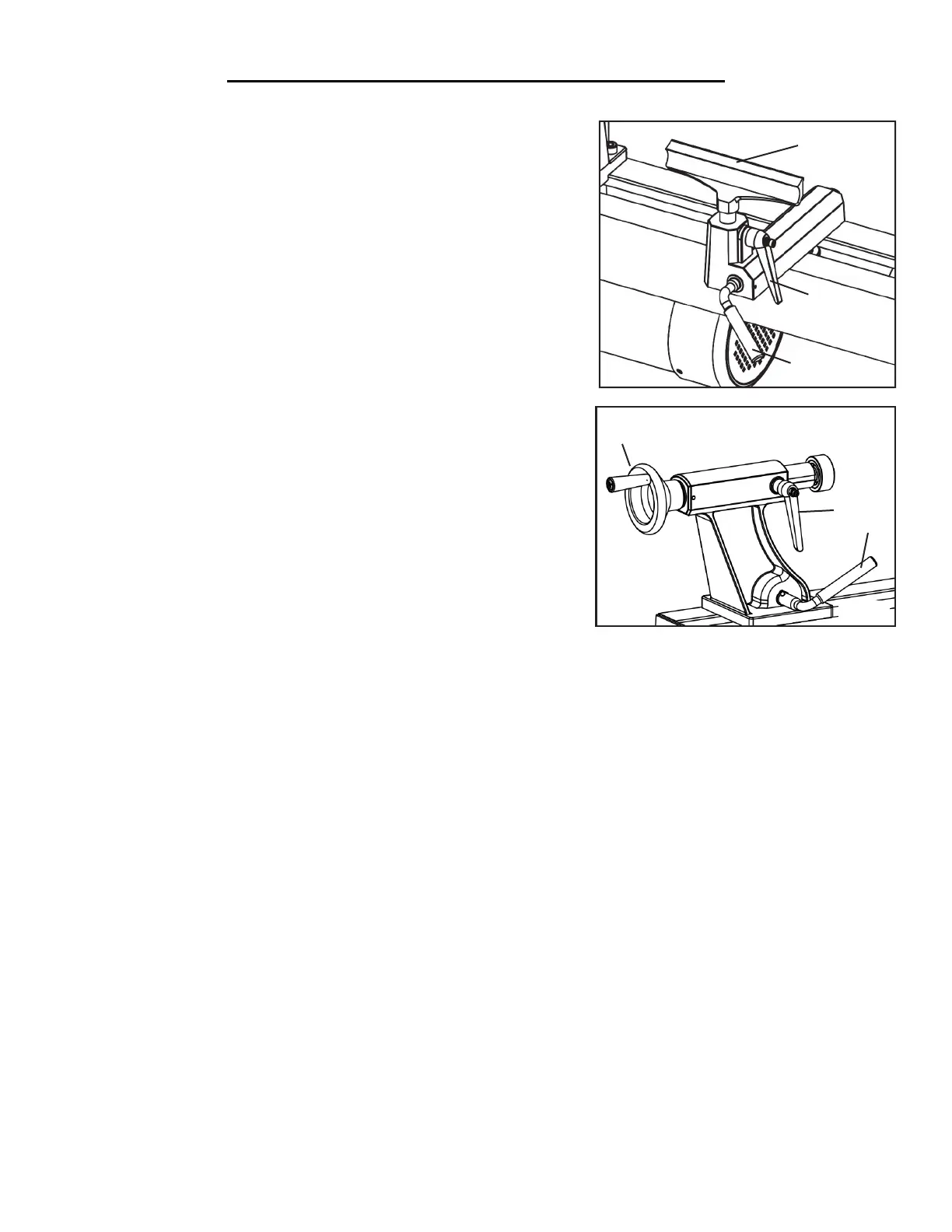
TOOL REST ADJUSTMENTS (Fig. K)
You can adjust the height, position and angle of the tool rest assembly
(Fig. K - 1) to suit your task at hand. To adjust the tool rest:
1. Loosen the small locking handle (Fig. K - 2) to raise and lower the
tool rest or to adjust its angle. Tighten the handle to secure the tool rest.
2. Loosen the locking lever (Fig. K - 3) on the tool rest base to slide
the base back and forth or to adjust its angle. Tighten the locking lever
firmly before operating the lathe.
NOTE: Adjust the height of the tool rest just below the center of the
workpiece, so that the tool will cut at the center of the workpiece.
TAILSTOCK ADJUSTMENTS (Fig. L)
1. Loosen the tailstock locking lever (Fig. L - 1) and slide the tailstock
into the desired position. Retighten the locking lever.
2. Loosen the quill locking handle (Fig. L - 2) to unlock the tailstock
quill. Use the handwheel (Fig. L - 3) to advance and retract the quill.
Retighten the quill locking handle.
Fig. K
2
3
1
1
2
3
Fig. L
 Loading...