ASSEMBLY & ADJUSTMENT
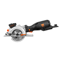
UPPER BLADE GUIDES ADJUSTMENT (Fig. I & J)
The upper blade guides need to be readjusted after every blade
change or blade tracking adjustment.
1. Upper Thrust Bearing (Fig. I - 1):
Loosen the upper right screw (Fig. I - 2) using the S4 hex wrench
to adjust the position of the thrust bearing running along the back
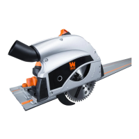
of the blade (Fig. I - 1). The bearing should be positioned 0.5 mm
from the back of the blade (Fig. J). Retighten the screw (Fig. I - 2).
2. Upper Side Guides (Fig. I - 5):
Loosen the two set screws (Fig. I - 4) using the S2 hex wrench
to adjust the two side guides at either side of the blade. The side
guides should be positioned 0.25 mm away from the blade (Fig. J).
Retighten the set screws (Fig. I - 4).
Loosen the lower right screw (Fig. I - 3) using the S4 hex wrench.
Move the screw to position the side guides 1 to 2 mm from the
teeth of the blade (Fig. J). Retighten the screw (Fig. I - 3).
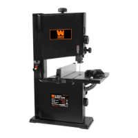
LOWER BLADE GUIDES ADJUSTMENT (Fig. J & K)
The lower blade guide needs to be readjusted after every blade
change or blade tracking adjustment.
1. Open the lower wheel cover. The table might need to be re-
moved for easier access to the adjustment screws.
2. The procedure is the same as adjusting the upper guides. Loos-
en the lower screw (Fig. K - 2) to adjust the thrust bearing 0.5 mm
from the back of the blade. Loosen the upper screw (Fig. K - 1) to
adjust the side guides 1 - 2 mm from the teeth of the blade. Loosen
the two set screws (Fig. K - 3) to adjust the side guides 0.25 mm
away from the either side of the blade.
3. Close the lower wheel cover.
11
Fig. I
Fig. J
Fig. K
Fig. L
4
3
5
2
1
2
3
1
3
1
2
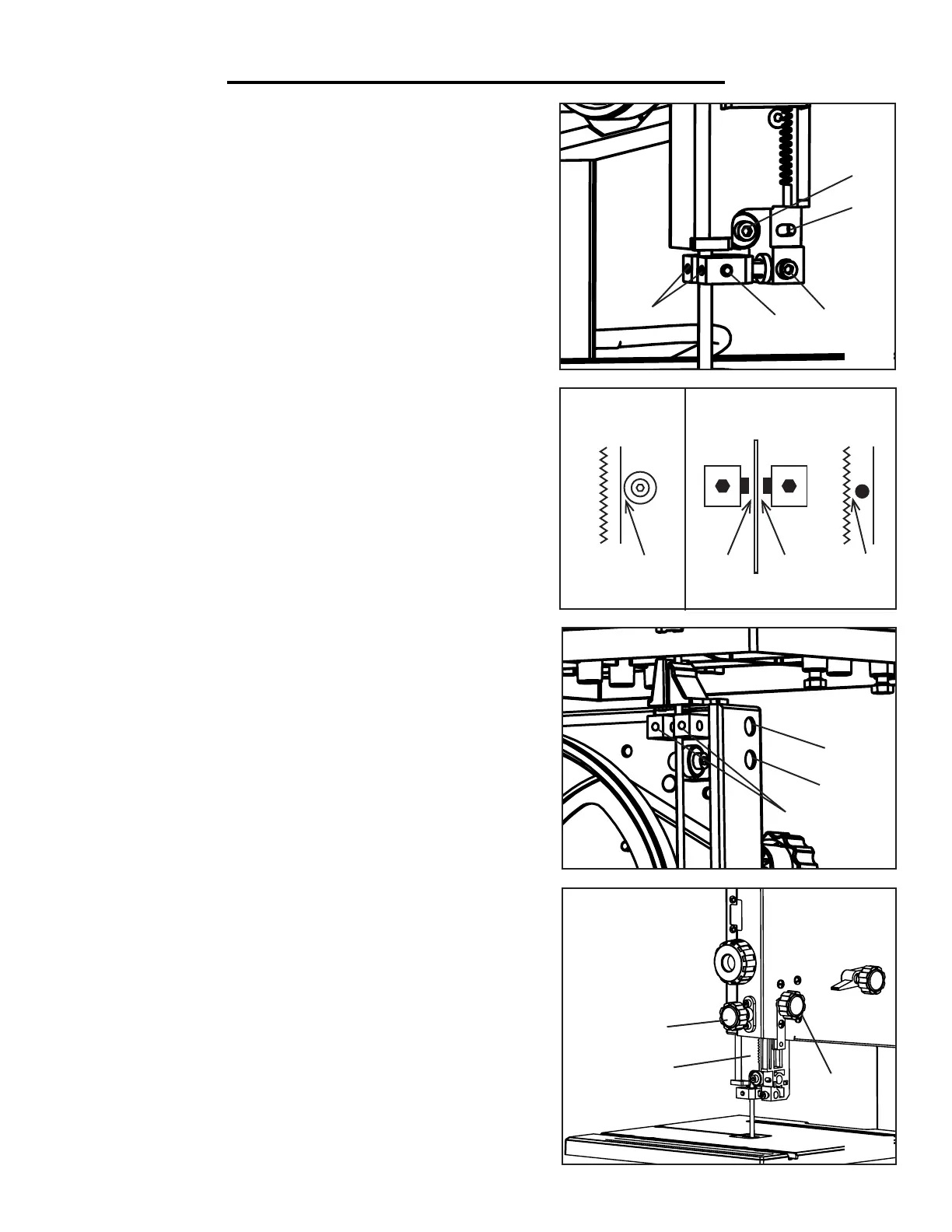
BLADE GUARD ADJUSTMENT (Fig. L)
The height of the upper blade guard (Fig. L - 1) should be adjusted
prior to every operation to accommodate the height of the work-
piece. NOTE: The blade guard should be no more than 1/8 of an
inch from the upper edge of the workpiece.
1. Loosen the blade guard locking knob located on the back of the
saw (Fig. L - 2).
2. Turn the blade guard adjustment knob (Fig. L - 3) to adjust
the height of the blade guard. Lock the upper blade guide locking
knob to secure the guard in place once the desired height has been
reached.
Side Guides
Thrust Bearing
0.25 mm
0.5 mm
1-2 mm
0.25 mm
 Loading...