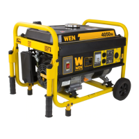
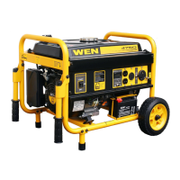
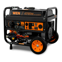
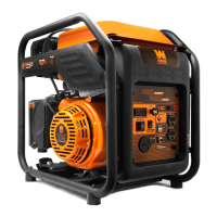
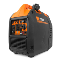
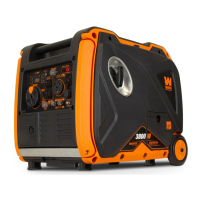
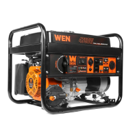
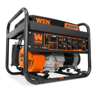
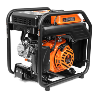
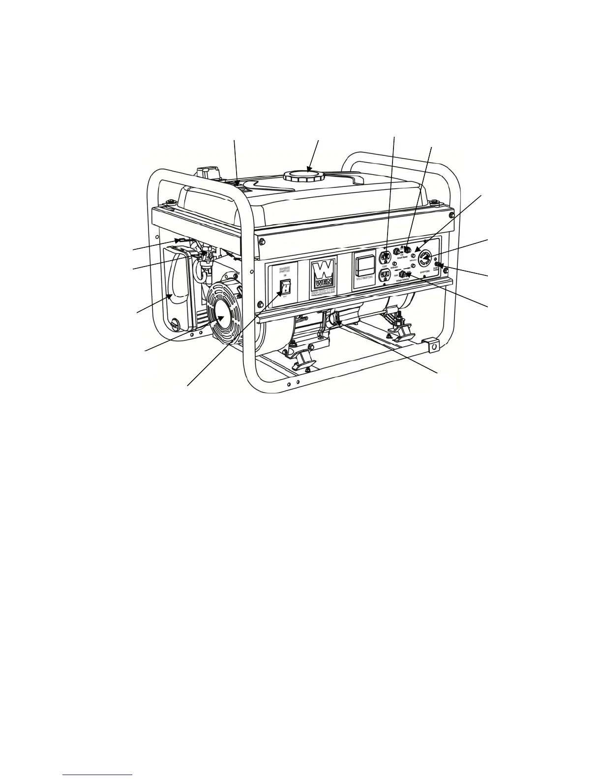
GENERATOR COMPONENTS
Please familiarize yourself with the locations and functions of the various components and controls
of your generator.
8
9
3
7
6
1 2
4
5
14
13
11
12
10
(1) Fuel Gauge- Indicates the amount of fuel in the
tank.
(2) Fuel Cap- Access to the fuel tank for adding
fuel.
(3) 120 Volt AC Duplex Receptacle- To connect
electrical devices that run 120 Volt, 60 Hz, single
phase, AC current.
(4) Circuit Reset Buttons- Reset buttons that
protect the generator from electrical overload.
(5) Power Indicator-Green lights that turn on to
indicate the output of power to each receptacle.
(6) 240/120 Volt AC Receptacle- To connect
electrical devices that run 120 and/or 240 Volt, 60
Hz, single phase, AC current.
(7) Ground Terminal- Connect grounding wires
here to properly ground unit.
(8) Voltage Selector-To switch between 120 and
240 Volt output.
(9) Oil Fill and Dipstick- Location for checking and filling
engine oil.
(10) Engine Switch- To start/stop engine.
(11) Recoil Starter- Pull-cord for starting engine.
(12) Air Cleaner- A removable, cleanable, sponge-like
element that limits the amount of dirt pulled into the engine.
(13) Fuel Valve- Allows fuel to enter engine.
(14) Choke Lever- Adjusts the amount of air let into the
engine.
7
 Loading...