ASSEMBLY & ADJUSTMENTS
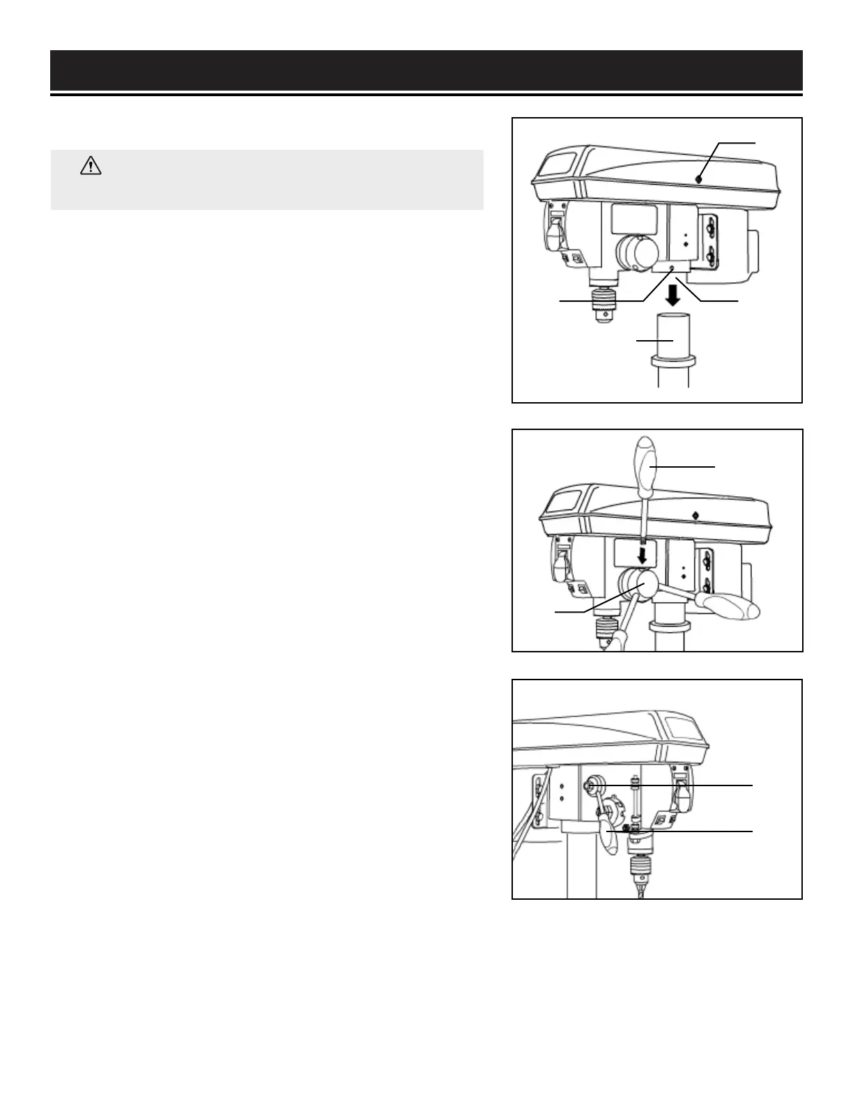
DRILL PRESS HEAD TO COLUMN (FIG. 5)
1. Carefully lift the drill press head assembly (Fig. 5 - 1) and
position it over the column (Fig. 5 - 2).
2. Place the mounting opening (Fig. 5 - 3) on the drill press
head over the top of the column. Make sure the drill press
head is seated properly on the column.
3. Align the direction of the drill press head with the direction
of the base and the table.
4. Tighten the set screw (Fig. 5 - 4) using the included hex
wrench.
FEED HANDLES (FIG. 6)
1. Insert the three feed handles (Fig. 6 - 1) into the threaded
openings on the feed hub (Fig. 6 - 2).
2. Manually tighten the handles into the openings. Use an
adjustable wrench (not included) to grip the flats on the
handles and fully tighten them.
NOTE: When using the drill press, one or two of the feed
handles may be removed if an unusually-shaped workpiece
interferes with the handle rotation.
SPEED HANDLE (FIG. 7)
1. Insert the speed handle (Fig. 7 - 1) into the threaded opening
on the speed hub (Fig. 7 - 2).
2. Manually tighten the handle into the openings. Use an
adjustable wrench (not included) to grip the flats on the
handles and fully tighten them.
12
Fig. 5
Fig. 6
Fig. 7
1
2
34
1
2
1
2
WARNING: The drill press head is heavy. To avoid
injury, two people should lift it into position.
 Loading...