ASSEMBLY
Carefully remove the tool and any accessories from the box. Make sure that all items listed in the packing list are
included. If any part is damaged or missing, please contact our customer service at (800) 232-1195, M-F 8-5 CST.
All of the parts for assembly should be accounted for before beginning the assembly.
PACKING LIST
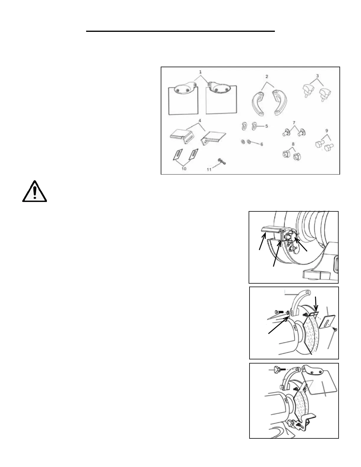
1. Eye Shield Assembly (2)
2. Eye Shield Arm (2)
3. Locking Knob M5 (2)
4. Tool Rest (2)
5. Lock Washer 6 (2)
6. Flat Washer 6 (2)
7. Carriage Head Screw M6x14 (2)
8. Tool Rest Knob M6 (2)
9. Hex Head Bolt M6x30 (2)
10. Spark Deflector (2)
11. Screw, Flat Washer, Spring Washer Kit (2)
WARNING: To avoid injury from unexpected starting or electrical shock, do not plug the power cord
into a source of power during unpacking and assembly. This cord must remain unplugged whenever
you are adjusting/assembling the grinder.
TOOL REST ASSEMBLY
1. Place the left tool rest (Fig. 1 - 1) over the tool rest bracket (Fig. 1 - 2).
2. Align the left tool rest with the hole on the bracket and slide the carriage
head screw through from the left side.
3. Screw the tool rest knob into place (Fig. 1 - 3)
4. Adjust the tool rest within 1/16 in. of the grinding wheel. To adjust this dis-
tance, loosen the knob and move the tool rest.
5. Assemble the right tool rest in a similar manner.
SPARK DEFLECTOR AND EYESHIELD ASSEMBLY
1. Place the spark deflector against the right wheel guard and secure into place
using a screw (Fig. 2 - 1). Adjust the spark deflector within 1/16” (0.0625”) of
the right grinding wheel and tighten the screw.
2. Attach right shield arm to the right wheel guard using a bolt and washer and
secure into place (Fig. 2 - 2).
3. Attach the right eye shield to the right shield arm and tighten the locking
knob into place (Fig. 3).
4. Attach spark deflector and eye shield to the left guard in a similar manner.
Fig. 3
Fig. 2
1
2
3
Spark
Arrestor
Screw
Bolt
Washer
Right Shield
Arm
1
2
Locking
Knob
Eye
Shield
9
Fig. 1
 Loading...