KNOW YOUR ELECTRIC ROUTER
ASSEMBLY AND ADJUSTMENT
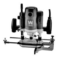
8. POWER CONTROL
Press down the trigger to start the router. Always ensure you are holding
the router properly before starting the tool. Your router is built with a
lock-on button (Fig. 5). To lock the switch ON, press the trigger all the
way down and then press down the lock-on button. To stop the router,
press the trigger until the lock-on button pops out. Then release the trig-
ger.
This router is equipped with a soft start function for safety operation.
When the router is switched on, the motor will slowly speed up until it
reaches the set speed. This gives you time to adjust your grasp on the
handles and gain control of the router.
9. SPINDLE LOCK BUTTON
Press down the spindle lock button (Fig. 6) to lock the spindle when
tightening the collet nut. Make sure to release the spindle lock button
before operation.
10. 1/2" COLLET & NUT ASSEMBLY
The 1/2" collet & nut assembly allows you to easily install router bits
with 1/2 inch shank. Insert the bit and tighten the nut with the included
wrench. Loosen the collet nut to uninstall the bit. To install a 1/4" bit,
Lock-On Button
Trigger
9
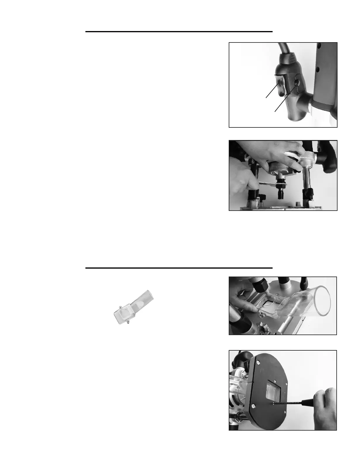
DUST EXTRACTION
1. Loosen the plunge lock lever, bring up the router to the maximum
height and lock the plunge lock lever (Fig. 2).
2. Place the dust extraction duct over the base and align the holes (Fig. 7).
NOTE: The dust extraction duct can be installed in either direction but
it is recommended to install with the outlet facing the back side of the
router for easier operation.
3. Attach it with the two screws from underneath the base (Fig. 8).
4. Connect the dust extraction duct to the dust hose.
What you need:
• Dust Extraction Duct
(with two screws)
Fig. 5
Fig. 6
Fig. 7
Fig. 8
first insert the bit into the 1/4" shank adapter and then insert the shank adapter into the collet & nut assembly. Fully
tighten the nut and check that the router bit is secure before turning on the router.