12
SETTING THE TABLE DISTANCE
WARNING: To avoid trapping the workpiece or
fingers between the table and the sanding disc, the
table edge should be set at about 1/16 inch away
from the sanding disc.
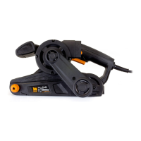
1. You can check the table distance with a 1/16” drill bit: try
to insert the bit between the table and the disc, and it should
barely fit into the space (Fig. 5). If adjustment is needed, fol-
low the instructions below.
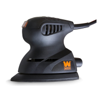
2. Loosen the six hex bolts under the table support brackets
(Fig. 6).
3. Using the 1/16" drill bit as a spacer, place it between the
sanding disc and the inner edge of the table. Move the table
into position against the drill bit.
4. Hold the table in place and tighten the six hex bolts.
5. Remove the drill bit.
SQUARING THE TABLE
To ensure accurate end sanding, the work table must be
square to the sanding surface prior to operation. Follow the
steps below to make sure your table is square with the sand-
ing disc at the 0° setting.
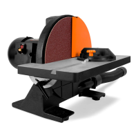
1. Loosen the two bevel locking handles and slide the table
into the 0° position (Fig. 7, indicated on the bevel scale).
Tighten the two locking handles.
2. Place a square against the sanding disc and the table. Check
if the surface of the table is square to the disc.
3. If adjustment is needed, loosen the two bevel locking han-
dles and slide the table against the edge of the square so that
ASSEMBLY & ADJUSTMENTS
Fig. 5
Fig. 6
Fig. 7
it is perpendicular to the sanding disc. Tighten the two bevel locking handles.
4. Using a Phillips head screw driver, loosen the screw securing the bevel pointer and adjust it to point to 0° on the
bevel scale. Tighten the Phillips head screw.
5. Recheck the square.
WARNING: To prevent serious injury from accidental operation, make sure the power cord is discon-
nected from the power source and the tool is turned OFF before assembly or making any adjustments.
 Loading...