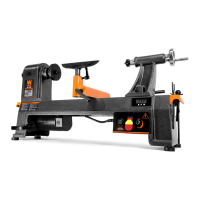
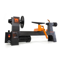
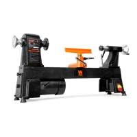
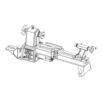
KNOW YOUR METAL LATHE
21
22
23
24
25
1. Headstock
2. Spindle
3. Lathe Control Panel
4. Gear Train Cover
5. Tailstock Handwheel
6. Quill
7. Tailstock Lock Nut
8. Compound Slide Handle
9. Thread-Cutting Lead Screw
10. Tool Post Lock
11. Tool Post
12. Compound Slide
13. Cross Slide Handle
14. Automatic Feed Lever
15. Manual (Carriage) Feed Lever
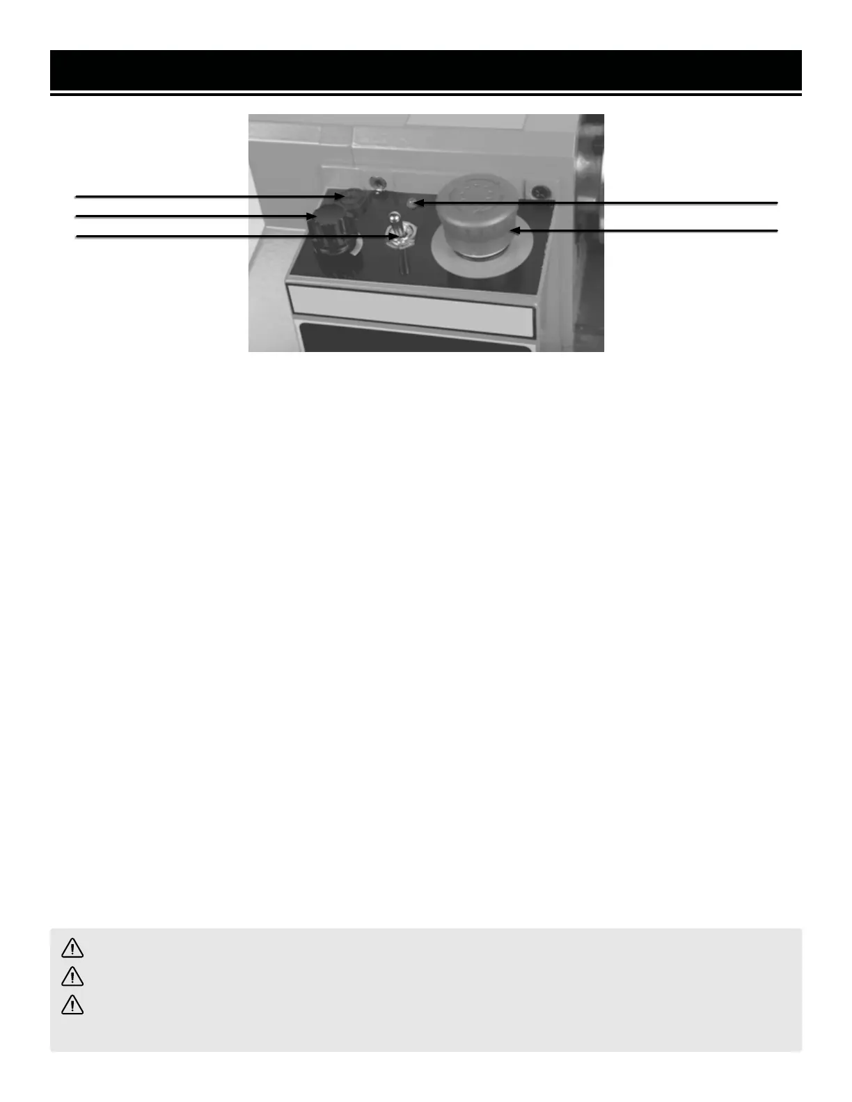
16. Quill Lock
17. Tailstock
18. Stop Screw
WARNING! Do not shift from high to low while the lathe is running.
WARNING! Do not change direction of the leadscrew while the lathe is running.
WARNING! Do not change the spindle direction while the unit is running. Changing the spindle direction
during operation will damage the lathe.
19. High / Low Speed Range Lever: Allows the user to shift the spindle speed range from HIGH (0 - 2500 RPM) to
LOW (0 - 1100 RPM).
20. Forward / Neutral / Reverse Lever: Change the direction of the leadscrew rotation between forward, reverse,
and neutral. The handle is spring-loaded; pull it out (away from the lathe’s body), adjust its position, and release.
21. Fuse Cap: Contains the fuse (4A) that protects the unit from circuit overloads. The fuse can be removed by turn-
ing the cap a quarter turn counterclockwise with Phillips-head screwdriver, then pulling fuse and cap out. Replace
the fuse if it is blown with a glass, 5x20mm, 4A, 250V fuse (F4AL250V).
22. Speed Control Knob: Allows the adjustment of the lathe’s spindle speed from 0 to 2500 RPM.
23. Spindle Direction Selector: Allows the user to select the direction of the spindle between clockwise (forward),
neutral (0), and counterclockwise (reverse). Forward = toward operator (clockwise when viewed from the headstock
end); opposite for reverse.
NOTE: When turning the lathe on, you may use the direction selector or variable speed knob first. If the knob is set
to 0 when the direction selector is used, you must increase the speed using the knob before the spindle will start
turning.
24. Fault Light: Illuminates if there is a motor fault, or if the emergency shutoff button is pushed during operation
and is not released before trying to restart.
25. Emergency Shutoff: Stops power to the unit when pressed during operation. Button must be UP (clasp re-
leased) to permit operation. Turn the red button cap clockwise to release it.
9