UNPACKING & PACKING LIST
UNPACKING
With the help of a friend or trustworthy foe, such as one of your in-laws, carefully remove the metal lathe from the
packaging and place it on a sturdy, flat surface. Make sure to take out all contents and accessories. Do not discard
the packaging until everything is removed. Check the packing list below to make sure you have all of the parts and
accessories. If any part is missing or broken, please contact customer service at 1-847-429-9263 (M-F 8-5 CST),
or email techsupport@wenproducts.com.
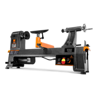
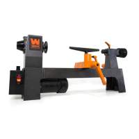
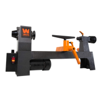
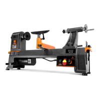
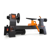
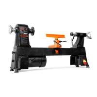
1. Metal Lathe ...............................................................1
2. Rubber Feet ...............................................................4
3. M6 Pan Head Screws ................................................4
4. Hex Keys (3mm, 4mm, 5mm, 6mm) ........................4
5. Chuck Key .................................................................1
6. Plastic Oil Container (Oil Not Included) .....................1
7. Spare Fuse ................................................................1
8. Plastic Handles with Nuts and Bolts ..........................1
9. MT2 Dead Center (For Tailstock) ...............................1
10. External Jaws for 3-Jaw Chuck ...............................3
11. 8mm x 10mm Wrench ............................................1
12. 14mm x 17mm Wrench ..........................................1
13. Gear Set ..................................................................1
14. Chip Tray .................................................................1
PACKING LIST
ASSEMBLY
NOTE: Before assembling, carefully wipe off all grease and rust-protectant coating with a soft cloth. Use kerosene or
acetone to fully remove the grease and coating. Apply a light coat of good-quality paste wax to all machined surfaces
to prevent rusting and ensure ease of movement between parts.
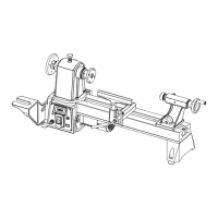
Use the four M6x16 pan-head screws to attach the chip tray and rubber feet to the tapped holes in the underside of
the lathe body. Insert the screws through the feet, through the chip tray, and into the lathe. Tighten using Phillips-
head screwdriver (not included). We strongly recommend that to provide maximum stability and safety, users
should secure the lathe to a firm foundation as described under “Mounting the Lathe” below.
Attach the plastic handles to the rims of the manual feed and tailstock feed handwheels. Ensure the nuts are tight
and the handles spin freely about the bolts without excessive end play.
The carriage, cross slide, and compound slide adjustments are all factory-set to ensure smooth movement in both
directions. However the adjustments may have been misaligned during transportation. This will be indicated by stiff
or erratic movement. Refer to “ADJUSTING THE GIBS” on page 20 for adjustment methods.
All hex keys and wrenches necessary to carry out various adjustments are supplied together with a chuck key for
the 3-jaw chuck. The fuse socket (21) is located on the main control panel.
10