AM 320-01-808
82
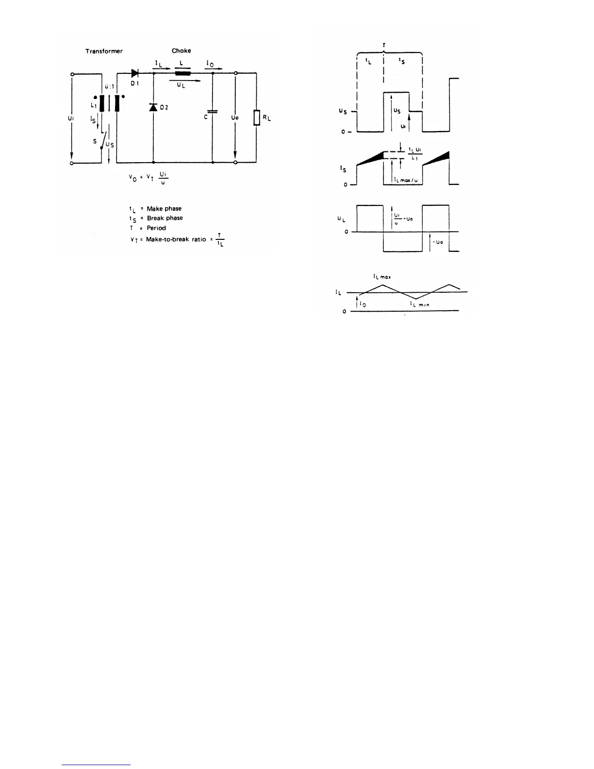
Fig. 1, Circuit diagram of a flow transducer Fig. 2, Voltage and current curves of the transducer
C. Peripherals
1. PS21 (Switching Power Supply)
The switching power supply PS 21 operates on the flow
transducer principle. This transducer principle makes it
possible to generate several output voltages with high
efficiency; the ripple of the output voltages is low. Fig. 1
shows the circuit diagram of such a transducer; Fig. 2
shows the respective (idealized) voltage and current curves.
During the make phase tL (S closed), the diode D 1 also
conducts current; energy is transferred to the load circuit
RL (hence the name flow transducer). Simultaneously,
choke coil L receives energy with the linearly increasing
current IL. Diode D 2 is not conducting.
If switch S is open, D 1 is polarized in the blocking
direction and therefore de-energized. Because of the energy
stored in choke coil L, the current proceeds through L and
hence through the load circuit in the same direction, the
now-conducting diode D 2 acting as a freewheeling diode.
Since UQUT is approximately constant, the choke current
again decreases linearly. C filters the starting voltage
UOUT. The magnetic energy forcibly absorbed from the
transformer during the make phase - represented by the
hatched magnetization current component of the switching
circuit Is - is undesired for the operation of the circuit. It
must be
absorbed by suitable means, transmitted back to DC source
U or otherwise utilized. Thus, the voltage at the transformer
or the switch (U
s
) is at the same time restricted.
Let us consider the actual circuit of the power supply PS
21. The major components of the circuit are easily
identified:
The transformer HFT 2 with the primary winding n1 and
the secondary windings n2, n3, n4. The windings of choke
coil PWR 1 are wound on the same core. This principle
permits relatively good regulation of the +/-15 V outputs.
The +5 V output is filtered by choke coil PWRI 2. D5. . D
8 are extremely rapid rectifier diodes and DD 1 is a high-
current Schottky dual diode. C 9, 10, 11 are electrolytic
capacitors with excellent high-frequency (HF) properties.
The role of the switch is played by a power FET, 0 1. The
network R 47, C 14, ZD 3, D 10 is selected so that the
magnetizing energy is reliably absorbed and the voltage at
the drain limited to about 90 V
There are various possibilities of keeping the output
voltage of a switching power supply on a constant level.
We chose a technique called "constant frequency, variable
make-to-break ratio".
 Loading...